Results
XtremeDSP Development Kit-IV. Host Computer. Virtex-4 User FPGA ( XC4VSX35-10FF668). Real-time Dose Control for Electron Beam Lithography. Virtex-II Clock FPGA (XC2V80-4CS144). Spartan-II Interface FPGA. UNIVERSITY OF KENTUCKY. PCI to User FPGA Interface Core.

Results
E N D
Presentation Transcript
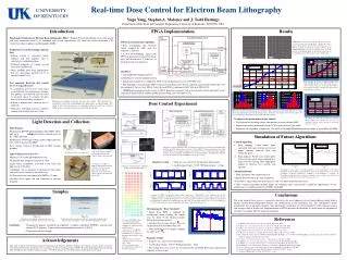
XtremeDSP Development Kit-IV Host Computer Virtex-4 User FPGA ( XC4VSX35-10FF668) Real-time Dose Control for Electron Beam Lithography Virtex-II Clock FPGA (XC2V80-4CS144) Spartan-II Interface FPGA UNIVERSITY OF KENTUCKY PCI to User FPGA Interface Core Ave. Dot Dia. = 227.6nm Ave. Dot Dia. = 225.8nm Ave. Dot Dia. = 214.5nm Ave. Dot Dia. = 226.9nm Ave. Dot Dia. = 227.2nm Ave. Dot Dia. = 233.8nm clock PMMA (~60nm) PMMA (~60nm) BB_RAITH Dose Control Logics Al (~60nm, E-beam evaporation) SiO2 (~40nm, sputtering) BB_FPGA User Interface Software Yugu Yang, Stephen A. Maloney and J. Todd Hastings Department of Electrical and Computer Engineering, University of Kentucky, KY40506, USA Scintillator (~450nm) Scintillator (~450nm) Dose Var. = 0 fC Dose Var. = ~24 fC Silicon Substrate Glass Substrate Glass Substrate Dose Var. = ~10 fC 40MS/s ADC Introduction FPGA Implementation Feedback clock ctrl data Dose Threshold • Light Sensing • Hamamatsu R4700U photomultiplier tube (PMT) offers gain up to with peak sensitivity through most of the visible spectrum. • Hamamatsu C4900 high voltage power supply provides 0 to -1250 V to power the PMT. • Low voltage electrical feed-through to EBL vacuum chamber • Light Collection System (LCS) • Material: UV-curable photopolymer resin • Ellipsoidal hole formed in rectangular solid. • Light source (scintillator) is located at one focus and light sensor at the other. • Aluminum (Al) is thermally evaporated on the inside surface of cavity to increase the reflectivity. • LCS increases the light captured by PMT by 12 times. • Shielded with copper foil and aluminum to prevent charging Fundamental limitation in Electron Beam lithography (EBL): Random Poisson distribution of electron arrival and resist interaction events [1-4], combined with system imperfections [5], limits the critical dimension (CD) control, line-edge roughness and throughput of EBL. Sig. from Scintillator ctrl Setup (a): sample (a) below mirror • PMT-current integration algorithm: • Start accumulating the electrical signal sampled by ADC once the exposure is initiated. • A new beam-blanking signal from FPGA is generated to turn off the beam once the desired dose is achieved, or keep the beam on if otherwise. • Traditional way of determining exposure dose: • E-beam current is measured before exposure and shot exposure time is calculated to yield desired dose. • Statistical properties of e-beam are not taken into consideration. • Other methods have been implemented that use intervening apertures [6-7] or emitter control [8-11]. 1mm 1mm Side (a) Side (b) Side (a) of LCS is covered with copper foil. Type (a) sample is placed underneath the hole where E-beam focuses through. Pro/E light collection system model Hardware testing Setup (b): sample (b) above mirror • LCS and power supply on sample holder with metal shield. • Side (b) of LCS is covered with copper foil. Type (b) sample sits on top of the mirror. • Power supply is shielded with a sheet of Al. • Hardware: • XtremeDSP Development Kit-IV • motherboard is used for implementation. • Signal from scintillator is sampled by ADC on the motherboard at a rate of 40 MS/s [12]. • The algorithm is translated into DSP system in System Generator software and then converted into binary file to be downloaded to Virtex-4 user FPGA. Virtex-II clock FPGA synchronizes ADC with user FPGA [12]. • DIMEScript language provides access to FPGA from host computer such as data transfer (“dose threshold” in the experiment reported here) and downloading binary design file to hardware [13]. Schematic of signal routing among modules on the board and the host computer Dots exposed at lower or higher average dose without feedback shows the same trend in std. of size as shown in the plot on the left when built-in dose variance increases. Average dot size increases as the base dose increases. • New approach: Real-time dose control for every exposed feature • A scintillating layer in resist stack emits several photons for each primary electron. The photons are collected and converted to electrical signal to estimate the dose that has been received by each pixel. • E-beam is blanked once sufficient dose is achieved. • Ultimately, individual electrons could be counted to overcome shot noise limit. • Determining the “Dose Threshold” • Signal from PMT is captured by oscilloscope when scanning the sample near the focus of the elliptical mirror before performing exposure. • Calculate the average voltage for the duration of desired dwell time (dt). • Dose threshold = (# of samples sampled by ADC in dt) * • Setup (a) was used to test the hardware functionality • Accelerating voltage: 10 keV; Working distance: ~24mm Schematics of elliptical mirror with video images captured in EBL chamber for dt Comparison of EBL system beam blanker signal (upper traces, “BB_RAITH” in the schematics above) with scintillator signal from the PMT (lower traces). A voltage of 0 indicates that the beam would be on in the absence of feedback control. (a) The dwell time was set to 10 ms (nominal dose 2095 fC) and the feedback system achieved the required dose (629 fC) by terminating the exposure early. (b) The dwell time was set to 1.5 ms (nominal dose 314 fC) and the feedback system extended the dwell times to achieve the desired dose. Illustration of feedback system for real-time dose control. The substrate to be patterned is coated with a scintillating layer that produces an optical signal. The signal is detected and processed to determine when each pixel has received sufficient dose so that the control system can stop the exposure. Dose Control Experiment SEM images of dots exposed with average dose of 0.09 pC. (a) Dose control was incorporated during exposure to achieve the desired dose level. The dwell time was set to 600 ms (nominal dose 0.28 pC, variance 0.04 pC) in the RAITH lithography software to avoid the effect of e-beam motion on the pattern shape. (b) Feedback control was not used during exposure. The variance of dose is 0.028 pC. dt Simulation of Future Algorithms Exposure was performed with average dose of 0.09 pC. When exposure was performed without dose control, the dot size spreads out more from the average value as the built-in dose variance increases. In contrast, dots exposed with dose control present a constant distribution variance. Samples Light Detection and Collection The change in nominal dose and the dose variance affects neither the average dot size, nor the standard deviation, when exposure is performed with dose control. • To improve the performance of dose control: • Use different accelerating voltage and aperture to achieve higher SNR. • Improve the quality of the mirror in the LCS to achieve better light yield. • Implement the algorithm at higher rate. The ADC on XtremeDSP motherboard can sample at speed up to 105 MHz. (a) (b) (a) (b) Type (a) Type (b) Investigation of the effects of system parameters on the performance of the control algorithms. (a) Normalized standard deviation of electrons required to expose one pixel as a function of photons produced by scintillator on the incidence of electron. (b) Normalized standard deviation of electrons required to expose one pixel as a function of sampling speed. Photons produced per electron is set to 5. Control algorithms Pulse counting: Count current pulse associated with each electron arrival until proper exposure achieved, then stop writing the pixel. Pulse analysis: Divide each current pulse by the average signal value produced by a single electron arriving. Once appropriate number of electrons have arrived, stop exposure. Scintillator emits light in an upwards direction or through the edges of the film. LCS sits above the sample. Light emitted from scintillator is reflected downwards by Al film. Glass substrate allows the light to reach to the LCS underneath the sample. Schematic of the experimental setup. The signal from PMT is routed through a transimpedance amplifier and ADC and finally processed by a Virtex-4 FPGA. The beam-blanking control signal from the EBL system (original connection shown with “X”) now provides the control signal for the logic, and a new signal from the FPGA controls the beam blanker. Transimpedance amplifier converts the negative current from PMT to 0-1V positive voltage. Results • Simulation Results • Both algorithms offer improvement in • standard deviation when the ratio of photons • to electrons is larger than 5 for pulse analysis, and 3 for pulse counting respectively. • Pulse counting algorithm depends highly on sampling speed, and provides significant improvement on the performance at sampling speed of 100 MS/s and higher. • Dot arrays in RAITH software • 7x7 dots in each field are separated by 0.9 mm to avoid damaging the scintillator under neighboring dots. • Same base dose is applied to all the fields in the same row and different dose variations are introduced intentionally to each column. • Base-dose factor increases vertically (bottom to top) from 50% to 200%. • Dose variance increases horizontally (left to right) from 0 to 29% of base dose. Conclusions Scintillator: • Composed of primary scintillator (p-terphenyl), secondary scintillator (POPOP), and polyvinyl toluene (PVT) polymer. Spin-coated from chlorobenzene solvent (C6H5Cl). • 420-nm emission wavelength The work reported here serves as a proof of concept for the novel approach of real-time feedback control of dose during electron-beam lithography without any modification of the patterning tool. The experimental results demonstrate that single-pixel exposures with intentionally varied dose are well controlled to yield constant variance and average value of feature size. Implementation on FPGA provides the flexibility to switch from one algorithm to the other, or combine both for future investigation. References • Exposure settings • Setup (b) was used to write the patterns • Accelerating voltage: 10 keV; Working distance: ~5mm • Dot settling time was set to 1 ms to eliminate the modulated dwell time affecting the exposure of the next dot. [1] G. P Patsis, et al., Microelectronic Engineering 87, 1575-1578, 2010. [2] P. Kruit, et al., Journal of Vacuum Science & Technology B 24, 2931-2935, 2006. [3] N. Rau, et al., Journal of Vacuum Science & Technology B 16, 3784-3788, 1998. [4] H. I. Smith, Journal of Vacuum Science & Technology B 4,148-153, 1986. [5] S. H. Lee et al., Photomask and NGL Mask Technology XVII, (SPIE, 2010),pp. 77480J. [6] M. A. McCord and A. D. Brodie, US Patent 7091486 (2006); M. Mankos, et al., US Patent 6555830 (2003); A. Yamada and Y. Oae, US Patent 5449915 (1995); Y. Fujikura, US Patent 4937458 (1990). [7] J. S. Kim, et al., Journal of Nuclear Science and Technology, 515-517, Jun 2008. [8] T. Rahman, et al., Journal of Vacuum Science & Technology B 25, 655-660, Mar-Apr 2007. [9] K. Wilder, et al., Journal of Vacuum Science & Technology B 17, 3256-3261, Nov-Dec 1999. [10] L. R. Baylor, et al., Journal of Vacuum Science & Technology B 20, 2646-2650, Nov-Dec 2002. [11] C. S. A. Durisety, et al., Analog Integrated Circuits and Signal Processing 48, 143-150, 2006. [12] Xilinx XtremeDSP Development Kit-IV Reference Guide, NT 107-0272 – Issue 3. [13] Nallatech DIMEscript User Guide, NT 107-0113 – Issue 3. Acknowledgements This work is supported by the National Science Foundation under Grant No. 0601351. Facilities and technical assistance for this work were provided by the University of Kentucky Center for Nanoscale Science and Engineering (CeNSE). We acknowledge Brian Wajdyk and Chuck May (CeNSE) for their valuable technical assistance. The FPGA design tools were donated by the Xilinx University Program.