Download
1 / 32
330 likes | 431 Vues
Explore the basics of spectral brightness, coherence, and optical phenomena in synchrotron radiation, with a focus on its wave nature and geometric optics versus wave optics.

E N D
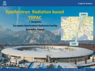
Spectral Brightness of Synchrotron Radiation Evan Walsh Mentors: Ivan Bazarov and David Sagan August 13, 2010
Basics • Accelerating charges emit electromagnetic radiation • For synchrotron radiation, the radiation is usually X-rays • One of the main goals of the new ERL at Cornell is to create one of the brightest X-ray sources in the world
What is Spectral Brightness? • In geometric optics, spectral brightness is defined as photon flux density in phase space about a certain frequency: • This means the number of photons per unit time per unit area per unit solid angle
Coherence • In the definition of spectral brightness, light is treated as a particle (a photon at some point in phase space) but what about the wave nature of light? • Coherence is a measure of how sharp the interference pattern formed by the light will be when passing through a slit
Geometric Optics vs. Wave Optics • Geometric optics is an easier way to treat light in that the propagation of photons is reduced to multiplying matrices • Geometric optics, however, does not account for wave phenomena such as diffraction and interference • To include wave properties, electric fields must be used
The Formula: The Wigner Distribution Function (WDF) • Spectral brightness for a single electron • Treats the electric field as a scalar • ω is the frequency at which the spectral brightness is being calculated • T is the time duration of the electric field • E is the electric field in the frequency domain • Brackets indicate taking an average in case of fluctuations • x is a vector containing the two transverse position coordinates in phase space • φ is a vector containing the two transverse direction coordinates in phase space • z is the longitudinal position along the optical axis
Eventual Goal • Calculate the Electric Field • Convolve the Electric Field with the Electron Phase Space • Calculate the Brightness of the Convolved Fields using the WDF
Step One: Electric Field of a Point Charge in the Time Domain • The equation for the electric field from a moving charged particle: • R is the vector from the particle to the observer • β is the ratio of the velocity of the particle to the speed of light • The dot signifies the time derivative of β (the acceleration divided by the speed of light) • u is a vector given by:
What does the ret stand for? • Light takes time to travel from the particle to the observer • By the time the observer sees the light, the particle is in a new position • The position at which the particle is when it emits the light is known as the retarded position and the particle is at this point at the retarded time
Retarded time • Use BMAD to findparticle trajectory • Use root findingmethods to solve:
Example: Bending Magnet • Electron trajectoryplotted againstretarded time • Electron trajectoryplotted againstobserver time
Step Two: Calculate the Electric Field in the Frequency Domain • Spectral Brightness requires the electric field in the frequency domain • To get this quantity, take a Fourier transform of the electric field in the time domain: • Numerically this is done with a Fast Fourier Transform (FFT)
Example: Bending Magnet • Frequency Spectrum of an Electron Travelling through a Bending Magnet
Example: Bending Magnet • Angular Radiation Distribution for an Electron Travelling through a Bending Magnet
Step Three: Plug in the Electric Field • This is known as a Wigner Distribution Function (WDF) • First introduced in 1932 by Eugene Wigner for use in quantum mechanics • First suggested for use in optics in 1968 by A. Walther • The above was suggested for synchrotron radiation by K.J. Kim in 1985
Polarization • Kim’s definition for spectral brightness treats the electric field as a scalar but in reality it is a vector • Polarization describes the way in which the direction of this vector changes • Types: Linear (horizontal, vertical, ±45º), right and left circular, elliptical
Stokes Polarization Parameters where • s0 is the total intensity • s1 is the amount of ±45º polarization • s2 is the amount of circular polarization (positive for right circular, negative for left circular) • s3 is the amount of horizontal and vertical polarization (positive for horizontal, negative for vertical)
Ray Stokes Parameters • Introduced by Alfredo Luis in 2004: where
Properties of the Ray Stokes Parameters: Dark & Fictitious Rays • S0 may take on negative values even though there cannot be negative intensity ; rays with S0 less then zero are called “dark rays” • Rays are not necessarily produced at a source; these rays are called “fictitious rays” • Dark rays and fictitious rays are essential to capture the wave nature of light
Properties of the Ray Stokes Parameters: Dark & Fictitious Rays • Example: Young Interferometer
Properties of the Ray Stokes Parameters: Conversion • The usual Stokes parameters can be obtained from the ray Stokes parameters by: • To get usual phase space distributions, integrate out one position and its corresponding angle (i.e. x and px or y and py)
Measuring the Stokes Parameters • It is impossible to directly measure the ray Stokes parameters but the usual Stokes parameters are obtainable empirically • To measure the Stokes parameters: • Send light through a retarder that adds a phase difference of φ between the x and y components of the electric field • Send the light from the retarder through a polarizer that only allows the electric field components at an angle of θ to be transmitted • The intensity of the light from the polarizer in terms of the Stokes parameters of the incident light is: I(θ,φ) = ½[s0+s1cos(2θ) +s2cos(φ)sin(2θ)+s3sin(φ)sin(2θ)
Properties of the Ray Stokes Parameters: Propagation • S stays constant along paraxial rays in free space • Huygen’s Principle: • Each point acts as a secondary source of rays • Rays are superimposed incoherently regardless of the state of coherence of the light • For propagation through homogeneous optical media, the incident Stokes parameters are multiplied by a Mueller matrix • For propagation through inhomogeneous optical media, the incident Stokes parameters are convolved with the WDF of the transmission coefficients
Example: Gaussian Beam Interference • Stokes parameters calculated from fields
Example: Gaussian Beam Interference • Stokes parameters calculated from WDF
Example: Gaussian Beam Interference • Phase space distribution x-px y-py
Example: Gaussian Beam Interference • Phase space distribution propagated in free space x-px y-py
Current Issues • It is hard to work with 4 dimensions in general so it would be preferable to use projections into the Stokes parameters or the x and y phase spaces separately • Propagation through optical media may not be as straightforward in this case and some information may be lost • A 4D array takes a large amount of memory • Possible Solution: Split the xy plane into sections and calculate the brightness in each separately – will use less memory but will take longer
Step Four: Spectral Brightness of Many Particles • Brightness Convolution Theorem: • The superscript zero means the brightness of the reference electron • The subscript e denotes the phase space coordinates of the reference electron • Ne is the total number of electrons • f is the distribution of electrons in phase space (a probability distribution function) • Works for a Gaussian distribution but not necessarily for an arbitrary distribution
Other Ideas to Calculate Ray Stokes Parameters for Many Particles • The electric fields from each particle need to be added together but it would take far too long to calculate these separately • Instead, find the field from a reference particle and either: • Taylor expand for particles at other positions and orientations • Include the change in position and orientation as a perturbation • Convolve the fields with the electron distribution and then calculate the WDF