Optimizing the Hydraulic Nanomanipulator P13371 for Enhanced Precision and Cost Efficiency
This document outlines the ongoing efforts to improve the Hydraulic Nanomanipulator P13371, focusing on enhancing precision, reducing costs, and addressing existing system limitations. Key objectives include redesigning components for better movement resolution and repeatability, developing advanced hydraulic actuation systems, and evaluating control interfaces. The project aims to meet competitive operational specifications while broadening access to nanoscience applications. The team includes experts in hydraulic systems, driver interfaces, and manipulator mechanisms, working collaboratively to achieve these goals.


Optimizing the Hydraulic Nanomanipulator P13371 for Enhanced Precision and Cost Efficiency
E N D
Presentation Transcript
Hydraulic Nanomanipulator P13371
Introductions • Customer Dr. Schrlau • Team Jacob Bertani Bridget Lally Avash Joshi Nick Matson Keith Slusser • Guide Bill Nowak
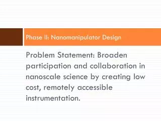
What Is a Nanomanipulator? • Ultra-high precision positioning instrument • Maneuver objects under high magnification, at the micro and nano scales • Primary customer uses: • Cell behavior for medical diagnostics
Project Objectives & Goals • Improve 12371 prototype and redesign where applicable • Improve overall nanomanipulator function to meet competitive operational specifications • Reduce price of nanomanipulator with respect to commercial devices • Broaden participation in nanoscience
Existing System (P12371) Controls Interface Subsystem
Existing System (P12371) Controls Subsystem
Existing System (P12371) Drive Subsystem
Existing System (P12371) Manipulator Subsystem
1st House of Quality Relationships: 9 = Strong 3 = Moderate 1 = Weak 0 = No Relationship
House of Quality Pareto Analysis • Top Specifications • Movement resolution • Position Repeatability • Manufacturing Cost • Joystick Control • Backlash reduction • If Top 8 of 16 Specs Met • 76% of customer needs satisfied
Existing System Evaluation (P12371) • Specs Unsatisfied • Backlash • Delay and rotation problems • Size • Weight • Specs Met • Resolution • Cost
Hydraulic Driver Concept Development Servo Motor Nano-precision actuator Stepper Motor Commercial Syringe
Stepper Motor • Current Driver • Already have working motors to test • Not the root cause of system performance issues • Easy to control • Evaluate existing motors and compare against other stepper motor options
Hydraulic Actuation Concept Development Piston Actuator • Fluid displaced through • the movement of a sealed ram
Hydraulic Actuation Concept Development Diaphragm Actuator • Pressure is transferred through the depression • of an immobile,flexible membrane seal
Future Hydraulic Actuation Plan • Both options are viable and will be evaluated in detailed design phase Diaphragm Seals Piston Seals
Manipulator Movement Concept Development • Ball Bearing Carriages • Sleeve Bearing Carriage • Low Profile Bearing Carriage • Friction Slider (current)
Sleeve Sliders • Pros • Reduced Friction • Reduced Vibration • Reduced Backlash • Cons • Cost
Retain Properties of Current System (P12371) • Resolution • 11 nm theoretical • 53 nm experimental • Cost • $1200 • Design Concept
Feasibility Analysis of Theoretical Resolution • Lead = 0.0125 in/rev = 0.3175 mm/rev • Microsteps/rev = 12,800 • 0.02185°/microstep
Issues to Improve in Current System (P12371) • Hydraulics • Backlash of 14 revolutions to change direction • Manipulator Mounting System • High friction causing backlash • Controls • Delay and rotation problems • Vibration in motor • Position un-repeatable • Machining Issues • Misalignment
Hydraulic System Issues • Air in lines • Fittings • Tubes
Air in Hydraulic Lines • Bulk modulus of water = 2,150 MPa • Bulk modulus of air = 0.142 Mpa • Assume: • Resulting Backlash • 15.75 Revolutions
Hydraulics Future Plan • Decrease tube diameter • Incorporate line bleeding valve • Replace barbed fittings Barbed Fitting Double Compression Fitting
Manipulator Mounting System Issues • Coefficient of Frictional of Slider too high • Misalignments
Feasibility Analysis of Sleeve Sliders • Total weight on bottom slider = 760 gms • Coefficient of Friction • Friction Slider = 1 • Sleeve Slider = 0.2 • Friction Slider = 8.2N • Sleeve Slider = 2.2N
Stepper Motor Issues • Controls • Un-fluid movement • Vibrations
Stepper Motor Control Future Plan • Evaluate Current System • Programming bugs • Different driver chip • Commercial control boards
Controls • Possible Design Changes • Different driver IC Chips • Improve board layout • Existing system • Functional • Low cost
Controls Future Plan • Evaluate existing code • Test existing microcontroller • Decide how to tackle live feed from camera
Preliminary Cost • Previous Manufacturing cost: $1,195.75 • Cost of suggested improvements: ~$300.00 • New sliders • Smaller diameter, thick walled tubing • New piston sleeves • Double compression fittings • Cost of items being removed: ~$110.00 • Estimated Manufacturing Cost: $1,400
Team Roles • Jacob Bertani– Lead Hydraulic Subsystem Engineer • Avash Joshi – Lead Driver / Hydraulic Interface Subsystem Engineer • Keith Slusser– Lead Manipulator Subsystem Engineer • Bridget Lally– Lead Controls Engineer • Nick Matson – Project Manager & Controls Engineer