Download
1 / 61
610 likes | 819 Vues
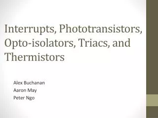
Interrupts, Phototransistors, Opto -isolators, Triacs , and Thermistors. Alex Buchanan Aaron May Peter Ngo. Reason for Interrupts.

E N D
Interrupts, Phototransistors, Opto-isolators, Triacs, and Thermistors Alex Buchanan Aaron May Peter Ngo
Reason for Interrupts • You might want a certain subroutine executed immediately after a request from an external device or from an internal program, providing certain conditions are met. • Interrupts do just this by suspending the execution of the current program in order to execute the subroutine
Request Checking Implementation • There are 2 ways of implementing Request Checking • Polling • Interrupts
Polling • Polling iteratively checks a device or registers for data. • This method of implementing request checking is cumbersome as it requires the MC to frequently suspend operations to check for new data from devices or registers.
Interrupts • Nothing is done until a Request is issued • Once issued, the CPU suspends execution of the main program until instructions in the Interrupt Service Routine (ISR) are executed • More efficient than constantly scanning devices or registers for new Data
Interrupts: Flow Mask Set Maskable Hardware Interrupt Complete Current Instruction YES 1 Software Interrupt (SWI) Stack Pointer NO 0 Wait For Interrupt (WAI) Complete Current Instruction SP -6 Condition Code Register SP -5 Accumulator B SP -4 Accumulator A Store MPU Registers to SP SP -3 Index Register (MS) SP -2 Index Register (LS) Hardware Interrupt YES Wait For Interrupt (WAI) SP -1 Program Counter (MS) SP Program Counter (LS) Maskable NO NO Set Mask (CCR4) (set to 1) YES Condition Code Register Is the Mask Set? 1 0 Load Interrupt Vector into PC X I BeginInterrupt Program (ISR) Interrupt Vector Clear Mask (CCR4) (set to 0) Back to Main Program
Stacking Order when an Interrupt Occurs Last value to be pulled from stack
Mask Set Interrupts: Flow: IRQ Example 1 Maskable Hardware Interrupt Complete Current Instruction YES 1 Software Interrupt (SWI) NO 0 Wait For Interrupt (WAI) Complete Current Instruction • If I bit in CCR is not set (I=0) and IRQ goes low for at least 2 cycle, the IRQ sequence is entered. • Internal registers stored to RAM (SP). • The IRQ mask bit set (I=1). • Data at FFF2 gets loaded into PCH • Data at FFF3 gets loaded into PCL • PC contents go out on address bus during 1. • Contents of the location addressed enter instruction register and are decoded as first instruction of interrupt routine. • If it is a more than 1-byte instruction, additional bytes enter MPU for execution. If not, go to next step • After execution, step 7 is repeated for subsequent instructions. This is repeated until “RTI” is executed. RTI tells the MPU that service is complete and that it may reload the registers and continue the main program from where it left off. Store MPU Registers to SP YES Hardware Interrupt Wait For Interrupt (WAI) NO Maskable NO Set Mask (CCR4) (set to 1) YES Mask Set 1 0 Load Interrupt Vector into PC BeginInterrupt Program (ISR) Clear Mask (CCR4) (set to 0) Back to Main Program
Interrupt Types 2 Types : • Maskable • 27 Maskable Interrupts • Split into Local and Global Types • Lower Priority than Non-Maskable • Priority between Maskable Interrupts can be adjusted via the HPRIO • Non-Maskable • 6 Non-Maskable Interrupts • Default Priority between Non-Maskable Interrupts that cannot be adjusted
Maskable Interrupts • IRQ • Real-Time Interrupt • Standard Timer Channel 0 • Standard Timer Channel 1 • Standard Timer Channel 2 • Standard Timer Channel 3 • Standard Timer Channel 4 • Standard Timer Channel 5 • Standard Timer Channel 6 • Standard Timer Channel 7 • Standard Timer Overflow • Pulse Accumulator A Overflow • Pulse Accumulator Input Edge • SPI transfer Complete • SCI system • ATD • Port J • CRG PLL Lock • CRG Self Clock Mode • Flash • CAN Wakeup • CAN Errors • CAN Receive • CAN Transmit • Port P • PWM Emergency Shutdown • VREG LVI • Global • I-bit in the CCR • Local • Interrupt enable bit • Follows a default priority arrangement • Any one interrupt can be promoted to higher priority using HPRIO register Any can be assigned the highest maskable interrupt priority...
Maskable Interrupts: IRQ Input • IRQ pin provides additional external interrupting source • IRQE bit in Options Register used to configure IRQ for Edge-Sensitive-Only Operation • IRQE = 0 IRQ is configured for low level sensitive operation • IRQE = 1 IRQ is configured for falling edge-sensitive operation
Used to elevate priority of any one maskable interrupt Default is IRQ Set by changing contents of HPRIO (Highest Priority Interrupt Register) Can only be written when I-bit is set HPRIO Register for Maskable Interrupts
HPRIO Register for Maskable Interrupts Address: $001F • PSEL[7:1] – Priority Select Bits • Selects one interrupts source to be elevated • Can only be written while I-bit in the CCR is set • Write the low byte of the maskable interrupt vector to HPRIO to elevate that maskable interrupt to the highest priority • Ex: writing $DE to HPRIO elevates the Standard Timer Overflow to highest priority (Standard Timer Overflow vector = $FFDE)
Non-Maskable Interrupts • 6 Non-Maskable Interrupts • Follows a default priority arrangement • Interrupts are not subject to global masking • Except XIRQ • Global mask is X in CCR POR of RESET pin Clock monitor reset COP watchdog reset Unimplemented instruction trap Software interrupt (SWI) XIRQ interrupt
Non-Maskable Interrupts:Unimplemented instruction trap • Generates interrupt request to Unimplemented instruction trap vector • Reinitializes stack pointer once interrupt service is completed • Left un-initialized, illegal opcode vector can cause infinite loop causing stack underflow
Non-Maskable Interrupts: Software Interrupt-SWI • Software instruction, thus cannot be interrupted until completed • Uninhibited by global mask bits in the CCR • Similar to other interrupts, sets I-bit upon servicing
Non-Maskable Interrupts: XIRQ • Enabled by TAP (Transfer accumulator A to CCR) which, while being unable to transfer the X-bit from 0->1 will convert the X-bit from 1->0 • After it is cleared, software cannot set X-bit (only set by the XIRQ or during Reset), thus XIRQ is non-maskable • Higher priority than any source maskable by I-bit • Both X and I bits are both automatically set by Reset or recognition of XIRQ interrupt • RTI restores X and I bit to pre-interrupt states
Interrupt Vectors Points to the memory address where the Interrupt Subroutine is stored Vector addresses can change depending on whether MON12 is in use or not • MON12 calls ISR’s specified by the user in the $0Fxx range • The microcontroller calls ISR’s specified in the $FFxx range.
Resets Forces MCU to: Assume set of initial conditions Begin executing instructions at predetermined starting address Initiated similarly to interrupts by using a vector to define the starting address of code to be run Resets completely stop execution of set of instructions
Sources of Resets Power on Reset (POR) Used only for power-up conditions Applying Vdd to MCU triggers POR circuit, initiates reset sequence, and starts internal timing circuit 4064 clock cycle delay after oscillator becomes active, allows clock generator to stabilize External Reset (RESET) System reset can also be forced by applying low level to RESET pin External source must hold reset pin low for a total of 6 cycles
Sources of Resets Computer Operating Properly (COP) Reset Protects against software failures, such as infinite loops Enabled by setting NOCOP bit in CONFIG register Timer rate controlled in OPTION Register. System E-clock is divided by 215 and further scaled by 1, 2, and 4 Clock Monitor Reset Protects against clock failure Set by CME control bit If enabled, the system resets if no MCU clock edges are detected
Process Flow out of Resets When Reset is triggered: Program counter loaded with contents of specified address from the vector S, X, and I bits are set in CCR MCU hardware is reset Checks for interrupts that have occurred
Standby Modes Suspends CPU operation until reset or interrupt occurs Used to reduce power consumption Two standby modes: WAIT STOP
Standby Modes: WAIT Opcode (WAI) Suspends CPU processing CPU registers are stacked On-chip crystal oscillator remains active Peripherals keep running Exit WAIT mode through external IRQ, XIRQ, or any internally generated interrupts
Standby Modes: STOP If S-bit in the CCR is 0, CPU goes into Stop mode If S-bit in the CCR is set, opcode is treated as NOP All clocks and internal peripherals are stopped Retains data in Internal RAM if Vdd is maintained CPU state and I/O pins are static
Standby Modes: STOP Exit STOP mode through external interrupts, pending edge-triggered IRQ, or RESET pin Recovering through XIRQ: X-bit is clear Returns to stacking sequence leading to normal XIRQ request X-bit is set Returns to instruction immediately following STOP instruction
Example Problem: 1ms interrupt • Write a routine to interrupt the MC9S12C32 after 1ms of elapsed time. Assume: • E = 8 Mhz, Prescaler = 1, MON12 in use • Use IOC3 channel to generate interrupt request • IOC3 will be used in output compare mode (OC3) • Standard timer channel 3 interrupt will be sent
Timer Module and Port T IOC3 will be used in output compare mode
Example Problem: 1ms interrupt 1: Assign valuesto labels Write a routine to interrupt the MC9S12C32 after 1msec of elapsed time. TC3HI EQU $0056 /* IOC3 output compare register */ TIOS EQU $0040 /* Input capture or output compare mode select */ TIEEQU $004C /* Timer interrupt enable register */ TFLG1 EQU $004E /* Timer interrupt flag register 2 */ TCTL2 EQU $0049 /* Timer control register 2 */ TCNT EQU $0044 /* Timer count register */ IOC3ISR EQU $2000 /* Location of IOC3 interrupt service routine */ IOC3VEC EQU $0FE8 /* Location of IOC3 interrupt vector */ BIT3HI EQU %00001000 /* Bit 3 set HIGH, all others LOW */ DLYIOMS EQU 8000 /* Number of delay cycles. 8000 cycles = 1ms */ ORG $1000 SEI /* Set I bit in CCR to mask interrupts during this routine*/ LDAA #BIT3HI /* BIT3HI = %00001000 */ STAA TIOS /* Configure IOC3 as output compare */ STAA TIE /* Enable IOC3 interrupt generation */ STAA TFLG1 /* Clear IOC3 interrupt flag*/ LDAB #%11000000 STAB TCTL2 /* Successful compare will set PT3 high */ LDX #IOC3ISR /* IOC3ISR = $2000, starting address of ISR */ STX IOC3VEC /* IOC3VEC = $0FE8, high byte ($20) stored in $0FE8, low byte ($00) stored in $0FE9 */ LDD TCNT /* Read current count from timer count register */ ADDD #DLYIOMS /* Add delay of 8000 cycles (=1ms) */ STD TC3HI CLI /* Clear I bit in CCR to allow maskable interrupts */ 2: Delay unwanted interrupts 3: Set timer registers 4: Store ISR 5: Set delay & unmask
Example Problem: 1ms interrupt Step 1: Assign values to labels TC3HI EQU $0056 /* IOC3 output compare register*/ TIOS EQU $0040 /* Input capture/output compare select*/ TIE EQU $004C /* Timer interrupt enable register*/ TFLG1 EQU $004E /* Timer interrupt flag register 2 */ TCTL2 EQU $0049 /* Timer control register 2*/ TCNT EQU $0044 /* Timer count register*/ IOC3ISR EQU $2000 /* Location of IOC3 ISR*/ IOC3VEC EQU $0FE8 /* Location of IOC3 interrupt vector*/ BIT3HI EQU %00001000 /* Bit 3 set HIGH, all others LOW*/ DLYIOMS EQU 8000 /* 8000 cycles = 1ms*/ • Treat these as named constants • EQU is an assembler directive (not a CPU instruction!) • Register addresses found in MC9S12C32 Device User Guide • Register details found in TIM_16B8C Block User Guide
Example Problem: 1ms interrupt Step 2: Delay unwanted interrupts ORG $1000 SEI /* Set I bit in CCR to mask interrupts */ /* Clear I bit at the end of our routine */ Alternatively, ORG $1000 LDD #$FFFF /* Set output compare reference to maximum */ STD TC3HI/* Store output compare reference */ • Understand why both work. What are the differences?
7 7 7 7 6 6 6 6 5 5 5 5 4 4 4 4 3 3 3 3 2 2 2 2 1 1 1 1 0 0 0 0 TCTL2 TIOS TFLG1 TIE OM3 IOS7 C7I C7F C6I OL3 C6F IOS6 IOS5 OM2 C5I C5F IOS4 OL2 C4F C4I IOS3 C3F C3I OM1 C2F C2I OL1 IOS2 C1I C1F IOS1 OM0 C0F OL0 IOS0 C0I $0049 $0040 $004E $004C Example Problem: 1ms interrupt Step 3: Write to timer registers LDAA #BIT3HI /* BIT3HI = %00001000 */ STAA TIOS /* Configure IOC3 as output compare (IOS3)*/ STAA TIE /* Enable IOC3 Interrupt bit (C3I)*/ STAA TFLG1 /* Clear IOC3 Interrupt Flag bit (C3F) */ LDAB #$C0 /* #$C0 = #%11000000 */ STAB TCTL2 /* Successful compare will set PT3 high */ • Configure desired settings using the timer registers
Example Problem: 1ms interrupt Step 4: Store ISR LDX #IOC3ISR /* IOC3ISR = $2000, starting address of ISR*/ STX IOC3VEC /* IOC3VEC = $0FE8, high byte ($20) stored in $0FE8 and low byte ($00) stored in $0FE9 */ • In this example, ISR is located in $2000 • Standard timer channel 3 interrupt vector is $0FE8 (hi) : $08FE9 (lo) when MON12 is in use
Example Problem: 1ms interrupt Step 5: Set delay and interrupt LDD TCNT /* Read current count from timer count register*/ ADDD #DLYIOMS /* DLYIOMS = 8000. 8000 cycles = 1ms delay*/ STD TC3HI CLI /* Clear I bit */ • TCNT is a 16-bit up-counter based on the bus clock • Read in count from TCNT and add 8000,store contents in IOC3 output compare register • Clear I bit in CCR to enable maskable interrupts • Approximately 1ms after this section, a Standard timer channel 3 interrupt request will be sent to the CPU
PhotoTransistors*, Opto-Isolators*, Triacs, and Thermistors* = USED IN ME 4447/6405
Phototransistors • Behave like regular transistors, but: • Use light-sensitivecollector-base junctionto control collector-emitter current (ICE) • Base often unconnected,otherwise biased to adjust sensitivity to light • Small collector-emitter leakage current whenno light is incident, called dark current
Phototransistor Structure and Packaging http://www.radio-electronics.com/info/data/semicond/phototransistor/photo_transistor.php
Phototransistor Application: Obstacle Detection • Adjust baffle length to vary detection range • Use IR LED and Photodiode to avoid visible light interference • Use multiple sensors in a row to detect narrow obstacles
Phototransistors: Additional Notes • Must be properly biased (as with regular transistors) • Used in linear and saturation/cut-off regions • Sensitive to temperature changes • Must be protected against moisture • Hermetic packaging more expensive, but more tolerant of severe environments than plastic packaging
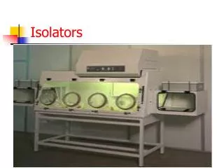
Optoisolators • Combines IR LED with IR photodiode • Operates similar to relays • Used to control high voltage devices • Excellent noise isolation because switching circuits are electrically isolated • Eliminates need for common ground between circuits
Optoisolators are like relays Optoisolator Relay
Optoisolator Structure • Glass dielectric separates input from output Planar Silicon dome
Optoisolator Application • Transmitting analog or digital signals between circuits, esp. with mismatched voltages, noise issues, inductive loads • Arduino isolated from relay drivers: To Arduino To Arduino http://arduino-info.wikispaces.com/RelayIsolation
Optoisolators: Additional Notes • Non-transistor optoisolators exist • Resistive optoisolator (photoresistor output) • Diode optoisolator (photodiode output) • Optoisolated SCR (thyristor output) • Optoisolated TRIAC (TRIAC output) • Solid-state relay • Relevant parameters for comparison: • Current Transfer Ratio (output current/input current) • Maximum output voltage • Input current, required for activating input transmitter • Bandwidth • Speed
Triacs (Triode for Alternating Current) • Conducts current in either direction when triggered,until current drops below holding current threshold • Bidirectionality makes TRIACs excellent AC switches • Can handle large power flows (hundreds of amps / thousands of watts) • Effectively based on thyristors