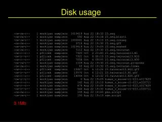
Disk Memory
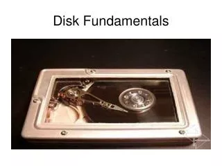
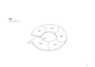
Disk Memory. Topics Disk Memory Structure Disk Capacity. class10.ppt. Disk Geometry. Disks consist of platters , each with two surfaces . Each surface consists of concentric rings called tracks . Each track consists of sectors separated by gaps. tracks. surface. track k. gaps.

Disk Memory
E N D
Presentation Transcript
Disk Memory • Topics • Disk Memory Structure • Disk Capacity class10.ppt
Disk Geometry • Disks consist of platters, each with two surfaces. • Each surface consists of concentric rings called tracks. • Each track consists of sectors separated by gaps. tracks surface track k gaps spindle sectors
Disk Geometry (Muliple-Platter View) • Aligned tracks form a cylinder. cylinder k surface 0 platter 0 surface 1 surface 2 platter 1 surface 3 surface 4 platter 2 surface 5 spindle
Disk Capacity • Capacity: maximum number of bits that can be stored. • Vendors express capacity in units of gigabytes (GB), where 1 GB = 10^9. • Capacity is determined by these technology factors: • Recording density (bits/in): number of bits that can be squeezed into a 1 inch segment of a track. • Track density (tracks/in): number of tracks that can be squeezed into a 1 inch radial segment. • Areal density (bits/in2): product of recording and track density. • Modern disks partition tracks into disjoint subsets called recording zones • Each track in a zone has the same number of sectors, determined by the circumference of innermost track. • Each zone has a different number of sectors/track
Computing Disk Capacity • Capacity = (# bytes/sector) x (avg. # sectors/track) x • (# tracks/surface) x (# surfaces/platter) x • (# platters/disk) • Example: • 512 bytes/sector • 300 sectors/track (on average) • 20,000 tracks/surface • 2 surfaces/platter • 5 platters/disk • Capacity = 512 x 300 x 20000 x 2 x 5 • = 30,720,000,000 • = 30.72 GB
The read/write head is attached to the end of the arm and flies over the disk surface on a thin cushion of air. By moving radially, the arm can position the read/write head over any track. Disk Operation (Single-Platter View) The disk surface spins at a fixed rotational rate spindle spindle spindle spindle spindle
Disk Operation (Multi-Platter View) read/write heads move in unison from cylinder to cylinder arm spindle
Disk Access Time • Average time to access some target sector approximated by : • Taccess = Tavg seek + Tavg rotation + Tavg transfer • Seek time (Tavg seek) • Time to position heads over cylinder containing target sector. • Typical Tavg seek = 9 ms • Rotational latency (Tavg rotation) • Time waiting for first bit of target sector to pass under r/w head. • Tavg rotation = 1/2 x 1/RPMs x 60 sec/1 min • Transfer time (Tavg transfer) • Time to read the bits in the target sector. • Tavg transfer = 1/RPM x 1/(avg # sectors/track) x 60 secs/1 min.
Disk Access Time Example • Given: • Rotational rate = 7,200 RPM • Average seek time = 9 ms. • Avg # sectors/track = 400. • Derived: • Tavg rotation = 1/2 x (60 secs/7200 RPM) x 1000 ms/sec = 4 ms. • Tavg transfer = 60/7200 RPM x 1/400 secs/track x 1000 ms/sec = 0.02 ms • Taccess = 9 ms + 4 ms + 0.02 ms • Important points: • Access time dominated by seek time and rotational latency. • First bit in a sector is the most expensive, the rest are free. • SRAM access time is about 4 ns/doubleword, DRAM about 60 ns • Disk is about 40,000 times slower than SRAM, • 2,500 times slower then DRAM.
Logical Disk Blocks • Modern disks present a simpler abstract view of the complex sector geometry: • The set of available sectors is modeled as a sequence of b-sized logical blocks (0, 1, 2, ...) • Mapping between logical blocks and actual (physical) sectors • Maintained by hardware/firmware device called disk controller. • Converts requests for logical blocks into (surface,track,sector) triples. • Allows controller to set aside spare cylinders for each zone. • Accounts for the difference in “formatted capacity” and “maximum capacity”.
I/O Bus CPU chip register file ALU system bus memory bus main memory bus interface I/O bridge I/O bus Expansion slots for other devices such as network adapters. USB controller graphics adapter disk controller mouse keyboard monitor disk
Reading a Disk Sector (1) CPU chip CPU initiates a disk read by writing a command, logical block number, and destination memory address to a port (address) associated with disk controller. register file ALU main memory bus interface I/O bus USB controller graphics adapter disk controller mouse keyboard monitor disk
Reading a Disk Sector (2) CPU chip Disk controller reads the sector and performs a direct memory access (DMA) transfer into main memory. register file ALU main memory bus interface I/O bus USB controller graphics adapter disk controller mouse keyboard monitor disk
Reading a Disk Sector (3) CPU chip When the DMA transfer completes, the disk controller notifies the CPU with an interrupt (i.e., asserts a special “interrupt” pin on the CPU) register file ALU main memory bus interface I/O bus USB controller graphics adapter disk controller mouse keyboard monitor disk