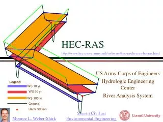
Modeling Inline Structures using HEC-RAS Version 3.1
This guide explains how to model in-line structures like gated spillways, overflow weirs, and dams using HEC-RAS. The modeling process is similar to bridges and culverts, with options for various gate types and weir shapes. Chapter references and step-by-step instructions are provided for easy implementation.

Modeling Inline Structures using HEC-RAS Version 3.1
E N D
Presentation Transcript
In Line Structures • Can be used to model in-line gated spillways, overflow weirs, drop structures, and dams. • Modeling method is very similar to bridges and culverts. • Weir shapes are either ogee or broad crested. • Gates are either radial (tainter) or vertical lift (sluice). • Up to 10 groups of gates with up to 25 identical gates per group are allowed for each in line weir. • Identical gates must have same type, size, elevation, and coefficient. • Uncontrolled overflow area is also an option.
Cross-Section Locations Suggested cross-section locations are the same as for bridges and culverts.
In Line Structure Typical Cross-Section 2 with ineffective flow areas defined.
In Line Structure Typical Cross-Section 3 with ineffective flow areas defined. Uncontrolled Spillway
In Line Structure Begin by selecting InLine Structure button from Cross-Section Editor. Select Lateral Structure button from Cross-Section Editor for lateral weirs.
In Line Structure Brings up window similar to culvert and bridge windows.
In Line Structure Must add structure as first step.
In Line Structure Brings up window to input cross-section location of the structure (weir)
In Line structure Adds a plot of the upstream cross-section to the window. Note you can edit the upstream cross-section from this button.
In Line Structure Click on the Weir/Embankment button... Which brings up the Weir Editor Window
In Line Structure After filling in the data...
In Line Structure … the plot is updated to show the embankment.
In Line Structure Click on the Gate button... Which brings up the Gate Editor Window
In Line Structure After filling in the data ... Default values shown C Free Flow Condition TE BE HE C Under free flow conditions the orifice cofficient is not used. Orifice flow occurs with the submerged condition.
In Line Structure … the plot is updated showing the gates.
Chapter 8 of the Hydraulic Reference Manual describes the hydraulic computations through gated spillways. Chapter 6 of the User’s Manual provides explanation for the various fields of the Inline Gate Editor.
Each profile modeled separately 2 gate groups All gates opened same height