PC Hardware Basic Guide
Learn about microprocessors, logic gates, number systems, and system buses in this comprehensive module. Explore different types of processors and essential concepts for choosing, installing, and troubleshooting hardware. Improve your knowledge of CPU technology!


PC Hardware Basic Guide
E N D
Presentation Transcript
PC Hardware Basic Guide Module 5 - Processors
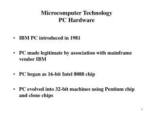
Module 5 - Processors • Overview • It is a single chip CPU. • It is an electronic component integrated with thousands and millions of transistors for performing arithmetic and logic operations. • The first processor under Advanced Technology is 80286. 80386, 80486 and the other Pentium processors. • Lesson Covered in this Module • Microprocessors • Advanced Processors • Choosing, Installing and troubleshooting a processor
Lesson 1 - Microprocessors • Introduction • A single chip CPU is called as Microprocessor • The CPU is made of two units namely the Arithmetic and Logic Unit and the Control Unit • It performs functions like executing the instructions given by the user program, controlling the I/O operations and the functions of peripheral devices
Lesson 1 - Microprocessors • Topics Covered in this Lesson • Microprocessors • Logic Gates • Number Systems • System Bus • 8085 Microprocessor • 8086 Microprocessor • 8088 Microprocessor • Support Chips used in 8088
Topic 1 – Microprocessor • The Arithmetic and Logic Unit (ALU) is used for performing Arithmetic and logic operations • The Arithmetic operations are addition, subtraction, multiplication and division. • The logic operations are taking decision based on same conditions. • Block diagram of Microprocessor
Topic 2 – Logic Gates • AND Gate • AND gate is a logic gate which produces an output “1” if both the inputs are “1”. • OR Gate • The output of OR gate is logic 1 if any one of its input is logic 1.
Topic 2 – Logic Gates • NOT gate or Inverter • If the input is logic 1 the output is 0 and vice versa. • XOR Gate • The output of XOR gate is one if one input is complement of the other.
Topic 2 – Logic Gates • NAND gate • The output is logic 1 if at least one input is logic 0. • The Register unit is used to store data. • The control unit controls operations like generating the control signals for reading, and writing data to memory or I/O devices.
Topic 3 - Number Systems • The different numbers systems in use are • Decimal Number System which has numbers in the range 0 to 9 • Octal Number System which has the numbers in the 0 to 7 • Binary Number System which has the numbers 0 and 1 • Hexadecimal Number System which has the numbers in the range 0 to 9 and A to F
Topic 3 - Number Systems • Decimal to Binary Conversion • For example: (29)10 converted to binary 29/2 = 14 remainder 1 14/2 = 7 remainder 0 7/2 = 3 remainder 1 3/2 = 1 remainder 1 1/2 = 0 remainder 1 • (Decimal) 27 = Binary (11101)2 • Binary to Decimal Conversion • For example: (11101)2 • Binary number (11101)2 = ( Decimal) 16+8+4+0+1= 29
Topic 3 - Number Systems • Hexadecimal Number System • The hexadecimal numbers are 0 to 9 and A to F. Continued….
Topic 3 - Number Systems • Hexadecimal to Binary conversion • (1A)16 = (0001 1010)2 • The binary value for 1 is 0001 • The binary value for A is 1010 • Binary to Hexadecimal Conversion • The binary number (0001 1010)2 • (0001)2 is 1; (1010) 2 is A • The hexadecimal value is thus (1A)16
Topic 3 - Number Systems • Hexadecimal to Decimal Number • The hexadecimal is first converted to binary and the binary number is then converted into decimal. • For example: Hexadecimal number (2B)16 • Step 1 - Hexadecimal number to binary (2B)16 = (0010 1011)2 • Step 2 - Binary number (0010 1011)2 to decimal 32+8+2+1=43 • Hexadecimal number (2B) 16 = (0010 1011)2= (43)10
Topic 4 - System Bus • The system bus is divided into three namely • Address bus • Data Bus • Control Bus • Address Bus - used to locate the unique locations to get the data • Data Bus - used to send data between devices and memory • Control Bus – It carries control signal from the processor to other devices or memory.
Topic 5 - Processors • 8085 Microprocessor • It is a 40 pin DIP package IC • It is an 8 bit processor • It is 3.125 MHz • It has16 bit address bus • Operates on +5V DC power supply • The pin diagram of 8085
Topic 5 - Processors • The signals present in the microprocessor are, • Address and Data Bus • The address bus of 8085 microprocessor is 16 bit. • The low order address lines AD0 to AD7 are multiplexed. • The High order A8 to A15 are dedicated for carrying the address. • Demultiplexed using Address Latch Enable (ALE) signal.
Topic 5 - Processors • Control and Status Signals • Control signals - RD and WR • Status signals - IO/M, S0 and S1 • Special signal - ALE to demultiplex the address and the data signals. • ALE (Address latch Enable) - Generates every time during the beginning of the operation. • RD (Read) - indicates that the selected memory location or the I/O device has to be read. • WR (Write) - indicates that data is available on the data bus and the data has to be written to the memory location or the I/O device Provided by the address bus.
Topic 5 - Processors • IO/M • Low signal it indicates a memory operation • High signal indicates an input output operation • Power Supply and Frequency Signals • Vcc– It is the power supply given to the microprocessor for its operation. • Vss– It is the ground reference • X1 and X2 are the two ends which are connected to the crystal • CLK (OUT) – used as a system clock for other devices.
Topic 5 - Processors • Interrupts and Externally Initiated Signals • Interrupt Request (INTR) signal is generated by the peripheral devices to catch the attention of the CPU. • Externally Initiated Signals • RESET (RESET IN and RESET OUT), HOLD, READY. • RESET IN: the microprocessor is reset • RESET OUT: used by the processor to reset the other peripheral devices • HOLD: generated by the DMA controller requesting the microprocessor to grant the bus.
Topic 5 - Processors • Serial I/O Ports • SID and SOD are two signals used for serial transmission. • SID is used to receive data bit by bit • SOD pin is used to output data bit by bit. • Flag Registers • Indicates the status of the Arithmetic and Logic operations. • The Flag registers present in 8085 microprocessor • Sign Flag • Zero Flag • Carry Flag • Auxiliary Carry Flag • Parity Flag
Topic 6 - Features of 8086 Microprocessor • 8086 is a 16 bit microprocessor • The clock speed varies from 4 MHz to 10 MHz • The data bus width is 16 bit • The width of the address bus is 20 bits. • Operates with +5V DC power supply • It is a 40 pin DIPP Package • It has a pipelined architecture • Does not provide a coprocessor support
Topic 7 - Features of 8088 Microprocessor • The data bus is 8 bit. • The clock speed supported is 4.77 MHz • It supports the 8087 coprocessor • Supports DMA data transfer • Supports pipelined architecture. • Supports nine flags • Provides large number of I/O ports up to 64K • The 8088 microprocessor operates in two different modes. • Minimum Mode • Maximum Mode
Topic 7 - Features of 8088 Microprocessor • The pin MN/MX decides the mode in which the processor can operate. • Under Minimum Mode, there is no coprocessor support.
Topic 7 - Features of 8088 Microprocessor • The MN/MX pin should be low to operate in Maximum mode.
Topic 7 - Features of 8088 Microprocessor • Basic units of 8088 Microprocessor • Bus Interface Unit (BIU) • Execution Unit (EU). • Functions performed by the BIU • I/O read and write • Memory read and write • Address generation and storing pre-fetched instructions • Functions performed by the EU • Decoding the instructions fetched by the Bus Interface Unit • Executing the instructions to generate the result
Topic 7 - Features of 8088 Microprocessor • Co-Processor 8087 • Used for performing arithmetic, trigonometric, exponential and logarithmic instructions. • So it is termed as Numerical Data Processor (NDP). • Working of 8087 Co-Processor • The results of floating point operations are desired to have 18 decimal digit accuracy.
Topic 7 - Features of 8088 Microprocessor • Interface between 8088 and 8087 in a PC • The address/data bus lines of he 8088 microprocessor are connected directly with the 8087 Co-Processor.
Topic 8 - Support Chips Used in 8088 • Different support chips present in the 8088 motherboard. • 8284 – Clock Generator is used to generate the clock • 8259-- Interrupt controller. • 8288 is the bus controller. • 8237 is the DMA controller. • 8253 is the programmable Timer • 8255 is the Programmable Peripheral Interface • 373 and 245 are address latches and buffer
Topic 8 - Support Chips Used in 8088 • Classification of Support Chips • Dumb Chip • No intelligence and it is not programmable • Does not have separate memory to store the commands and the controls • Function of the dumb chip is fixed and is according to the input • Smart Chip • It is programmable and has intelligence. • Separate memory to store the commands and the controls • Troubleshooting of a smart chip is complex
Topic 8 - Support Chips Used in 8088 • Programmable Interrupt Controller (PIC) – 8259A • It is used in the XT motherboard to generate an interrupt signal • PCI is an interface between the CPU and the device. • The XT motherboard supports one interrupt controller which can support eight devices
Topic 8 - Support Chips Used in 8088 • The AT motherboard supports two interrupt controllers (8259) for supporting 15 interrupts.
Memory Refresh Channel 0 Channel 1 Not Used FDC Channel 2 HDC Channel 3 Topic 8 - Support Chips Used in 8088 • Programmable DMA Controller 8237 • Inn XT motherboard only one DMA controller is present. • In AT motherboards, two DMA controllers are cascaded. • The DMA controller has four channels • Channel 0 is used for refreshing RAM • Channel 1 is not used • Channel 2 is used by Floppy Disk Controller for performing data transfer • Channel 3 is used by Hard Disk Controller for performing data transfer
Lesson 2 - Advanced Processors • Introduction • The advancement in technology brought many variations to the Extended Technology XT and the Advanced Technology was introduced • It is very much essential to identify the different processors, their features and the sockets or the slots where they can be connected.
Lesson 2 - Advanced Processors • Topics Covered in this Lesson • 80286 Processor • 80386 Processor and 80486 Processor • Types of Instruction Set • Pentium Processor • Processor Generations • Pentium MMX and Pentium PRO Processors • Pentium II Processors • Pentium Xeon Processors • Celeron Processors • Pentium III Processors • Pentium IV Processor • AMD Processor • Processor Identification
Topic 1 - 80286 Processor • The registers and the ALU is 16 bit. • The width of the address bus is 24 bit. • It operates with +5V DC • It operates in 8 MHz, 10 MHz and 12.5 MHz • It has Non-Multiplexed address/data bus
Topic 1 - 80286 Processor • There are four stage in executing an instruction. • The instruction execution in a pipeline.
Topic 2 - 80386 and 80486 Processors • Intel 80386 processor • It is a 32 bit microprocessor. • Two types are 80386 SX and 80386 DX. • They are real mode, protected mode and virtual 86 mode. • The 80386 SX has 24 address lines and the 80386 DX has 32 address lines • Supports instruction pipelining
Topic 2 - 80386 and 80486 Processors • Intel 80486 Processor • Two types • 80486 SX and 80486 SL • 80486 DX • 80486 DX2 • 80486 DX4 • It has inbuilt Numeric Data processor • It has a unified inbuilt cache memory
Topic 3 - Types of Instruction Set • Complex Instruction Set Computing (CISC) • This processors are provided with large number of complex instructions • Reduced Instruction Set Computing (RISC) • It has less number of transistors and is cheaper. • Explicitly Parallel Instruction Computing (EPIC) • It has combined features of both CISC and RISC. • Very Large Instruction Word (VLIW) • The VLIW type processors will be able to receive many instructions per word.
Topic 4 - Pentium Processors • Comparison
Topic 4 - Pentium Processors • Features of Pentium Processor • Pentium processor supports Superscalar architecture. • Supports Functional Redundancy Check. • Supports effective power management feature. • Supports multiprocessor
Topic 4 - Pentium Processors • Cyrix 686 Processor • The pin of the Cyrix processor was Pentium compatible and could be placed in SOCKET 7. • AMD Processors • The series of AMD processors • K5 processor • K6, K6-2, K6-3 processors • K7 Athlon processor.
Topic 5 - Processor Generations • The table shows the size of cache memory supported by different processors
Topic 5 - Processor Generations • Some of the specifications, the significance and example of processor.
Topic 5 - Processor Generations • The figure below shows the different generations of computers and the processors
Topic 6 - Pentium MMX and Pentium PRO Processors • Pentium MMX • It has on chip multimedia architecture. • Supports enhanced Pipeline feature • Operates with 2.8V • Intel Pentium PRO • Super pipelining Architecture • Integrated L1 Cache • Optimized performance for 32 bit code
Topic 7 - Pentium II Processor • It integrated MMX feature in it. • Runs at different speeds of 233 MHz, 266 MHz, 300 MHz, 333 MHz. • Supports 512 KB of L2 cache • Supports 32 KB of L1 cache • Supports 32 bit and 64 bit pipelined floating point unit