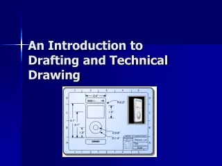
An Introduction to Drafting and Technical Drawing
270 likes | 1.14k Vues
Learn the principles of technical drawing used by architects, designers, and engineers. Discover the importance of accurate visual instructions in creating precise drafts for various applications.

An Introduction to Drafting and Technical Drawing
E N D
Presentation Transcript
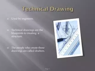
Technical Drawing Technical drawing, also known as drafting, is the academic discipline of creating standardized technical drawings by architects, interior designers, drafters, design engineers, and related professionals. Standards and conventions for layout, line thickness, text size, symbols, view projections, descriptive geometry, dimensioning, and notation are used to create drawings that are ideally interpreted in only one way.
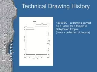
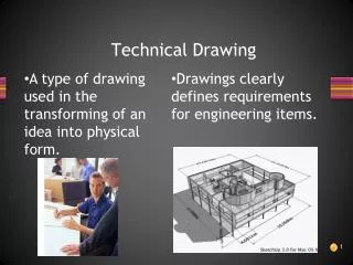
Why do we need Technical Drawings? Have you ever tried to assemble something without a diagram? You won’t get very far. Technical drawings are visual instructions used to help us determine the overall layout and design of what is being drafted. Ex. A floor plan of a house.
Artistic Drawings vs. Technical Drawings A technical drawing shows how an object should look, how it will be put together, or how it looks from different directions and is drawn to scale. Artistic drawings allow for distortion and artist’s interpretation.
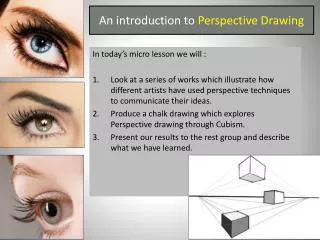
Pictorial Views A pictorial technical drawing is a 3-D view of an object. Some pictorial views are: • 1, 2, and 3 point perspective • Cabinet oblique and Isometric
Cavalier Oblique In cavalier oblique drawings, all lines (including receding lines) are made to their true length. Lines extend on a 45 degree angle
Cabinet Oblique In cabinet oblique drawings, the receding lines are shortened by one-half their true length to compensate for distortion and to approximate more closely what the human eye would see. It is for this reason that cabinet oblique drawings are the most used form of oblique drawings.
Orthographic Flash Presentation http://www.wisc-online.com/objects/index_tj.asp?objID=ENG19204
Be careful…Top and Front are the same, but the sides are not.
Your Task Draw 3 objects using the following techniques: • Oblique Drawing • Isometric Drawing • Single Point Perspective • Two-Point Perspective • Orthographic Drawing
Auxiliary View An auxiliary view is an angle at which one can view an object that is not one of the primary views for an orthographic projection. An auxiliary view is a view at an angle used to give deeper insight into the actual shape of the object.