Medium Access Control
This article explores the concept of Medium Access Control (MAC) within communication networks, detailing how it provides a mechanism for coordinating access to shared communication mediums. We discuss the distinction between logical link control and MAC, the role of MAC in managing collisions in broadcast environments, and the various approaches to medium sharing, including deterministic and random access methods. Additionally, we analyze specifications for channelization techniques like FDMA, TDMA, and CDMA, elaborating on their implementation for efficient data transmission in diverse traffic scenarios.

Medium Access Control
E N D
Presentation Transcript
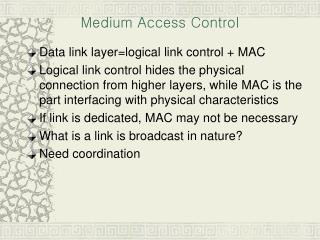
Medium Access Control • Data link layer=logical link control + MAC • Logical link control hides the physical connection from higher layers, while MAC is the part interfacing with physical characteristics • If link is dedicated, MAC may not be necessary • What is a link is broadcast in nature? • Need coordination
Multiple access communications 3 2 4 1 Shared Multiple Access Medium 5 M • Any transmission from any station can be heard by any other stations • If two or more stations transmit at the same time, collision occurs Figure 6.1
Wireless LAN: share wireless medium and require MAC Figure 6.6
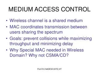
Medium Access Control • MAC: Medium access control or Multiaccess control or Multiple access control • MAC: protocols coordinating the use of shared resource (“channel”) • Classification • Centralized vs distributed • Deterministic vs random • Static vs dynamic • Reservation-based vs demand based • QoS based or fair sharing
Approaches to sharing transmission medium Minimize the incidence of collision to achieve reasonable usage of medium. Good for bursty traffic. Medium Sharing Techniques Static Channelization Dynamic Medium Access Control Partitioned channels are dedicated to individual users, so no collision at all. Good for steady traffic and achieve efficient usage of channels Scheduling Random Access Try and error. if no collision, that is good, otherwise wait a random time, try again. Good for light traffic. Schedule a orderly access of medium. Good for heavier traffic. Figure 6.2
Duplexing • Control transmissions in both directions • Forward (downlink) • Reverse (uplink) • Time division duplexing (TDD) • Forward and reverse use the same channel but at different time assignment • Time slots in a frame divided into uplink and downlink • Frequency division duplexing (FDD) • Forward and reverse transmissions use different frequency channels
Channelization (Deterministic MAC) • Resource available in the network will be shared • Time • Space • Frequency • Code • Classification • FDMA • TDMA • CDMA • SDMA
Channel 1 Channel 2 Bandwidth Channel 3 Channel 4 Time FDMA • A channel is assigned to a user for the entire duration of a call. No other user can access the channel during that time. When call terminates, the same channel is re-assigned to another user. • FDMA used in nearly all first generation mobile systems: AMPS (30 KHz channels), NMT, Japanese TACS/NTT
TDMA • The whole channel is assigned to each communicating user, but users are multiplexed in time domain. Each user is assigned a particular time slot, during which it communicates using the entire frequency spectrum • The data rate of the channel is the sum of data rates of all the multiplexed transmissions • Channel interference between transmissions in two adjacent slots, limits the number of users sharing the channel Channel 3 Channel 1 Channel 1 Channel 2 Channel 2 Channel 3 Channel 4 Bandwidth Time
CDMA • It’s a spread-spectrum technique, allows multiple users to share the same channel by multiplexing transmissions in code space. Different signals from different users are encoded by different codes (keys) and coexist both in time and frequency domains • A code is represented by a wideband pseudo noise (PN) signal • When decoding a transmitted signal at the receiver, due to low cross-correlation of (orthogonal) codes, other transmissions appear as noise. This property enables multiplexing of multiple transmissions on the same channel with minimal interference • Maximum allowable interference (from other transmissions) limits the number of simultaneous transmissions on the same channel All channels share bandwidth Bandwidth Time
CDMA • Spreading the signal can be performed using • Direct Sequencing (DS): the narrow band data signal is multiplied by a wideband pseudo noise (PN) signal (code). Multiplication in the time domain translates to convolution in the spectral domain, resulting in a wideband signal • Frequency Hopping (FH): the carrier frequency rapidly hops among a set of possible frequencies according to some pseudo random sequence (code). The set of frequencies spans a large bandwidth. Thus the bandwidth of the transmitted signal appears as largely spread
MAC efficiency • Suppose bit rate of medium is R, then number • of bits “wasted” in access coordination is 2tpropR. And suppose average length of packets is L. Then efficiency in use of the medium is: 1 L 1 Efficiency = = = tpropR • L + 2tpropR 1+2a 1 + 2 L a=tpropR / L i.e., the ratio of (one-way) delay-bandwidth product to the average packet length. Suppose a = 0.01, then efficiency = 1/1.02 = 0.98 a = 0.1, then efficiency = 1 / 2 = 0.50
Examples of efficiency • Ethernet (CSMA-CD): • Efficiency = 1/(1+6.44a) where a = tpropR/L. • Token-ring networks: • Efficiency = 1/(1+a’) where a = ring-latency in bits/L where ring-latency contains: • The sum of bit delays introduced at each ring adapter. • Delay-bandwidth product where delay is the time required for a bit to circulate around the ring.
Typical LAN structure and network interface card RAM RAM (a) A LAN connects servers, workstations, Printers, etc., together to achieve sharing • NIC is parallel with memory • but serial with network • 2. ROM stores the implementation of MAC • 3. Unique physical address burn into ROM • 4. A hardware in NIC recognizes physical, • broadcast & multicast addresses. • 5. NIC can be Set to “promiscuous” mode • to catch all transmissions. (b) Ethernet Processor ROM Figure 6.10
IEEE 802 LAN standards Network Layer Network Layer LLC 802.2 Logical Link Control Data Link Layer 802.11 Wireless LAN Other LANs 802.3 CSMA-CD 802.5 Token Ring MAC Physical Layer Various Physical Layers Physical Layer OSI IEEE 802 One LLC and several MACs, each MAC has an associated set of physical layers. MAC provides connectionless transfer. Generally no error control because of relatively error free. MAC protocol is to direct when they should transmit frames into shared medium. Figure 6.11
The MAC sublayer provides unreliable datagram service MAC MAC MAC PHY PHY PHY Unreliable Datagram Service Important: all three MAC entities must cooperate to provide datagram service, I.e., the interaction between MAC entities is not between pairs of peers, but rather all entities must monitor all frames. Figure 6.12
MAC MAC MAC PHY PHY PHY LLC provides three HDLC services: 1. Unacknowledged connectionless service, recall HDLC has unnumbered frames; 2. Reliable connection-oriented service in the form of HDLC ABM mode; 3. Acknowledged connectionless service, need to add two unnumbered frames to HDLC frame set. C A A C Reliable Packet Service LLC LLC LLC LLC can provide reliable packet transfer service Figure 6.13
LLC provides additional addressing, i.e., SAP (Service Access Point). Like PPP, LLC can • support several different network connections with different protocols at the same time. • Typical SAPs: IP: 06, IPX: E0, OSI packets: FE etc. • In practice, LLC SAP specifies in which buffer the NIC places the frame, thus allowing the • appropriate network protocol to retrieve the data. 1 byte 1 1 or 2 Destination SAP Address Source SAP Address Control Information Source SAP Address Destination SAP Address C/R I/G 1 7 bits 7 bits 1 I/G = Individual or group address C/R = Command or response frame LLC PDU structure and its support for several SAPs Figure 6.14
Header overhead: TCP & IP: >=20 LLC: 3 or 4 MAC: 26 IP IP Packet LLC PDU Data LLC Header MAC Header FCS MAC frame LLC PDU and MAC frame Figure 6.15
IEEE 802.3 MAC frame 802.3 MAC Frame 6 1 6 2 4 7 Destination Address Source Address Information FCS Pad Preamble Length SD Synch Start frame 64 to 1518 bytes • Destination address is either single address • or group address (broadcast = 111...111) • Addresses are defined on local or universal basis • 246 possible global addresses 0 Single address Group address 1 0 Local address 1 Global address Unicast address: a single host address, multicast address: a group of hosts, Broadcast address: all hosts. Figure 6.52
Random Access • Why random access? • Reaction time (i.e., 2 times of propagation delay) is very important for performance, e.g., in Stop-and-Wait, when reaction time is small (i.e., the ACK will arrive soon) the performance is very good, however, if reaction time is large, then performance is very bad. • Therefore, proceed the transmission without waiting for ACK and deal with collision/error after the fact, i.e., random access. • Three types of random accesses: • ALOHA, slotted ALOHA, and CSMA-CD
ALOHA • Basic idea: • let users transmit whenever they have data to be sent. • When collision occurs, wait a random time ( why? ) and retransmit again. • Differences between regular errors &collision • Regular errors only affect a single station • Collision affects more than one • The retransmission may collide again • Even the first bit of a frame overlaps with the last bit of a frame almost finished, then two frames are totally destroyed.
ALOHA random access scheme Suppose L: the average frame length, R: rate, X=L/R: frame time 1. Transmit a frame at t=t0 (and finish transmission of the frame at t0+X ) 2. If ACK does not come after t0+X+2tprop or hear collision, wait for random time: B 3. Retransmit the frame at t0+X+2tprop+B Two modes: collide only from time to time and snowball effect collision First transmission Retransmission t t0 t0+X t0-X t0+X+2tprop t0+X+2tprop Vulnerable period Backoff period: B Time-out Retransmission if necessary When collision occurs? Vulnerable period: t0-X to t0+X, (2X seconds) if any other frames are transmitted during the period, the collision will occur. Therefore the probability of a successful transmission is the probability that there is no additional transmissions in the vulnerable period. Figure 6.16
The performance of ALOHA • Let S be the arrival rate of new frames in units of frames/X seconds, • S is also the throughput of the system. • Let G be the total arrival rate in units of frames/X seconds, G • contains the new and retransmissions and is the total load. • Assume that aggregate arrival process resulting from new and • retransmitted frames has a Poisson distribution with an average • number of arrivals of 2G frames/2X seconds, i.e., (2G)k P[k transmissions in 2X seconds] = e-2G , k=0,1,2,… k! Therefore, the throughput of the system is: S=GP[no collision] =GP[0 transmission in 2X seconds] (2G)0 e-2G =G e-2G =G 0!
What results can be obtained from the graph? 1.peak value at G=0.5 with S=0.184 2.for any given S, there are two values of G, corresponding to the two modes: occasional collision mode with S G and frequent collision mode with G >> S 0.368 Ge-G S 0.184 Ge-2G G Throughput S versus load G for ALOHA and slotted ALOHA Figure 6.17
Slotted ALOHA • Synchronize the transmissions of stations • All stations keep track of transmission time slots and are allowed to initiate transmissions only at the beginning of a time slot. • Suppose a packet occupies one time slot • Vulnerable period is from t0-X to t0, i.e., X seconds long. Therefore, the throughput of the system is: S=GP[no collision] =GP[0 transmission in X seconds] (G)0 =G e-G =G e-G 0!
Slotted ALOHA random access scheme t0=(k+1)X First transmission Retransmission t (k+1)X =nX kX t0+X+2tprop t0+X+2tprop Backoff period: B Time-out Retransmission if necessary Vulnerable period: t0-X to t0 , i.e., X seconds long Figure 6.16
Peak value at G=1 with S=0.368 for slotted ALOHA, double compared with ALOHA. In LAN, propagation delay may be negligible and uncoordinated access of shared medium is possible but at the expense of significant wastage due to collisions and at very low throughput. Throughput of ALOHAs is not sensitive to the reaction time because stations act independently. 0.368 Ge-G S 0.184 Ge-2G G Throughput S versus load G for ALOHA and slotted ALOHA Figure 6.17
CSMA (Carrier sensing multiple access) • Problem with ALOHAs: low throughput because the collision wastes transmission bandwidth. • Solution: avoid transmission that are certain to cause collision, that is CSMA. Any station listens to the medium, if there is some transmission going on the medium, it will postpone its transmission.
Suppose tprop is propagation delay from one extreme end to the other extreme end of the medium. Station A begins transmission at t=0 A Station A captures channel at t=tprop A When transmission is going on, a station can listen to the medium anddetect it. After tprop, A’s transmission will arrive the other end; every station will hear it and refrain from the transmission, so A captures the medium and can finish its transmission. But in ALOHAs, it is X or 2X Vulnerable period = tprop In LAN,generally, tprop < X sense sense sense sense CSMA random access scheme Figure 6.19
Three different CSMA schemes • Based on how to do when medium is busy: • 1-persistent CSMA • Non-persistent CSMA • p-persistent CSMA
1-persistent CSMA sense channel when want to transmit a packet, if channel is busy, then sense continuously, until the channel is idle, at this time, transmit the frame immediately. If more than one station are sensing, then they will begin transmission the same time when channel becomes idle, so collision. At this time, each station executes a backoff algorithm to wait for a random time, and then re-sense the channel again. Problem with 1-persistent CSMA is “high collision rate”.
Non-persistent CSMA sense channel when want to transmit a packet, if channel is idle, then transmit the packet immediately. If busy, run backoff algorithm immediately to wait a random time and then re-sense the channel again. Problem with non-persistent CSMA is that when the channel becomes idle from busy, there may be no one of waiting stations beginning the transmission, thus waste channel bandwidth,
p-persistent CSMA sense channel when want to transmit a packet, if channel is busy, then persist sensing the channel until the channel becomes idle. If the channel is idle, transmit the packet with probability of p, and wait, with probability of 1-p, additional propagation delay tprop and then re-sense again
Throughput versus load G for 1-persistent (three different a=tprop/X ) S 0.53 1-Persistent CSMA 0.01 0.45 0.16 0.1 G 1 Figure 6.21 - Part 2
Throughput versus load G for non-persistent (three different a=tprop/X ) S 0.81 Non-Persistent CSMA 0.01 0.51 0.14 0.1 G 1 1-persistent is sharper than non-persistent. a=tprop/X has import impact on the throughput. When a approaches 1, both 1-persistent and non-persistent is worse than ALOHAs. Figure 6.21 - Part 1
CSMA-CD • When the transmitting station detects a collision, it stops its transmission immediately, Not transmit the entire frame which is already in collision. • The time for transmitting station to detect a collision is 2tprop. • In detail: when a station wants to transmit a packet, it senses channel, if it is busy, use one of above three algorithms (i.e., 1-persistent, non-persistent, and p-persistent schemes). The transmitter senses the channel during transmission. If a collision occurred and was sensed, transmitter stops its left transmission of the current frame; moreover, a short jamming signal is transmitted to ensure other stations that a collision has occurred and backoff algorithm is used to schedule a future re-sensing time. • The implication: frame time X >= 2tprop, , since X=L/R, which means that there is a minimum limitation for frame length.
A begins to transmit at t=0 B A B begins to transmit at t= tprop- B detects collision at t= tprop B A A B A detects collision at t= 2 tprop- The reaction time in CSMA-CD is 2tprop It takes 2 tprop to find out if channel has been captured Figure 6.22
When a is small, i.e, tprop << X, the CSMA-CD is best and all CSMAs are • better than ALOHAs. • When a is approaching 1, CSMAs become worse than ALOHA. • ALOHAs are not sensitive to a because they do not depend on reaction time. CSMA/CD 1-P CSMA Non-P CSMA max Slotted Aloha Aloha a = tprop /X Maximum achievable throughput of random access schemes Figure 6.24