Download
1 / 27
270 likes | 292 Vues
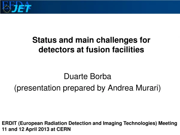
Status and main challenges for detectors at fusion facilities. Duarte Borba (presentation prepared by Andrea Murari). ERDIT (European Radiation Detection and Imaging Technologies) Meeting 11 and 12 April 2013 at CERN. Path to Fusion energy using Magnetic Confinement. (in 2040s).

E N D
Status and main challenges for detectors at fusion facilities Duarte Borba (presentation prepared by Andrea Murari) ERDIT (European Radiation Detection and Imaging Technologies) Meeting 11 and 12 April 2013 at CERN
Path to Fusion energy using Magnetic Confinement (in 2040s) Operation (1983 – Present) (in 2020s)
Operation with Deuterium-Tritium • Current Tokamak operation uses only Deuterium. The last large scale Deuterium-Tritium (DT) operation took place on JET in 1997, with a next DT operation at JET proposed for around 2015 in preparation of the ITER DT operation foreseen for 2026. • 2015 2026 • JET DT1 JET DT2 ITER DT • Radiation hardness of detectors and neutron measurements are key developments in fusion research in preparation of the next DT experiments on JET and on ITER. • This presentation focus on the on going developments at JET required for DT operation, which are also relevant for ITER, focussing on g-ray, x-ray, and neutron measurements.
Overview • Radiation Hard Hall probes for measurement of steady state magnetic fields • Advanced detectors for g-ray spectroscopy • Advanced detectors for neutron spectrometry • Advanced electronics for neutron and g-ray counting • Si on insulator detectors for neutral particle measurements • GEM detectors and polycapillary optics • Summary
Hall sensors resistance in radiation environment of neutron irradiation Sensor testing in ITER-relevant neutron fluxes is being performed in Nuclear reactors WWR-MPetersburg Nuclear Physics Institute,Russia IBR-2Joint Instituteof Nuclear Research,Dubna, Russia WWR-TsInstitute ofPhysical Chemistry,Obninsk, Russia LVR-15Nuclear Research Institute, Řež,Czech Republic
Hall sensors resistance in radiation environment of neutron irradiation Sensors sensitivity change vs. neutron fluence: 1 – radiation-resistant sensor; 2 – conventional sensor F = 1015 cm-2 → ΔS/S = 0.04% F = 1016 cm-2 → ΔS/S = 0.08% F = 1017 cm-2 → ΔS/S = 5% F = 1018 cm-2 → ΔS/S = 10% InSb-based sensors are operable up to neutron fluences F = 5·1018 cm-2=5 1022 m-2 which exceed maximum fluence in ex-vessel sensor locations at ITER
Radiation physical processes occurring in InSb-based Hall sensors under irradiation Methods for stabilizing the semiconductor sensor parameters: • Chemical doping of semiconductor materials (InSb, InAs) with the complex of doping impurities (donor, isovalent, rare-earth ones) up to optimal initial concentration of free charge carriers. • Radiation modification – preliminary introduction of certain number of radiation defects. Neutrons Fast Thermal Semiconductor Mutual compensation Radiation defects Nuclear doping Donors Acceptors Minimal sensor parameter drift (97,5% of possible reactions) (subject to correction with dedicated electronic methods)
Radiation-hard ex-vessel Hall Probe locations High stable Hall sensor 2mm Microsolenoid coil 6 Hall Probes with 18 Hall Sensors and 18 microsolenoids have been installed at JET Hall sensors
Gamma-ray spectrometry on JET Roof Lab The 3 gamma-ray JET spectrometers based on Bismuth Germanate (BGO) and NaI (sodium iodide doped with thallium) Scintillator detectors, 2 of them in the Roof Lab, one in a tangential view, have limitations in: -Low Count rate, <50 kHz (total rate including a large neutron background component) -Low Energy resolution > 7% for the 662 keV gamma-rays from 137Cs -Large neutron background sensitivity ~4m
Gamma-ray spectrometry on JET • Developments (goals and objectives) • Improved energy resolution: better that 0.2% in the case of the HPGe (high-purity germanium) detector • Improved time resolution. The key figure of merit is the count rate capability: it should exceed 0.5 MHz before pile-up and gain drifts begin to affect the detector response. • Substantial neutron background reduction: a factor >100 neutron flux attenuation will be achieved for one of the detectors with the use of a LiH (lithium hydride) neutron attenuator.
New Detectors installed in Roof Lab High-resolution and High efficiency HPGe spectrometer Lanthanum Bromide scintillator LaBr3(Ce) Gammas & Neutrons Gammas & Neutrons
HPGe Measurements in JET plasmas Sum of 7 JET discharges: (#73760-73770) where minority 3He ions n3He =1-5%, are accelerated using Ion Cyclotron Resonant Heating PICRH5-6MW tuned at w3He in D plasma with electron density ne=2-3 1019 m-3. 3He+12Cp+14N* (Q=4.8 MeV) • Good description of the 1.63 MeV and 2.31 MeV peak for T3He> 300 keV 13 M. Tardocchi et al, PRL 107 (2011) 205002
Demonstration of high counting rate LaBr3(Ce) Scintillator Lanthanum Bromide scintillator LaBr3(Ce) was tested at the nuclear accelerator facility in Romania for high counting rate experiments in preparation of the JET DT campaign. Measurement carried out at the Tandem Van der Graaf facility in Magurele (Romania). Spectrum of 10 MeV p beam on 27Al target Rate = 2.6 MHz Implication for JET: capability to handle g-ray counting rates > 1 MHz (important for JET DT experiments) with lower energy resolution than HPGe but better radiation hardness properties M. Tardocchi et al., IEEE Nuclear Science Symposium, Valencia, 2011 – contributed oral presentation M. Nocente et al., submitted to IEEE Trans. On Nucl. Science
Compact Neutron Spectrometer Development Construction and installation at JET of a dedicated compact neutron spectrometer”, composed of a Digital Pulse Shape Discrimination (DPSD) board, coupled to a NE213 scintillator detector provided with a LED for photomultiplier gain variation corrections
Compact Neutron Spectrometer JET Compact Neutron Spectrometer :Line of Sight Spilbine NE213 scintillator Detector is located in a bunker with an horizontal line of sight which has a significant component tangential
Compact Neutron Spectrometer Below is shown an example of optimization of the neutron / gamma rays separation settings in the LabView graphic environment (JET pulse No. 82723): g n
New Boards for Neutron and Gamma ray Cameras • The old neutron emission profile diagnostic (KN3) consists of two fan shaped arrays of collimators (10 horizontal + 9 vertical lines of sight. Each line of sight has 3 detector systems based on scintillators: • NE213 liquid scintillator with analog pulse shape discrimination (PSD) electronics for recording of 2.5 MeV and 14 MeV neutrons; • 2) BC418 plastic scintillator for 14 MeV detection; • 3) CsI(Tl) scintillator for gamma emission measurements in the energy range 0.2-6 MeV.
New Data Aquisition Boards for Neutron Cameras • Replacement of the analog PSDs and data acquisition/processing for the Neutron yield profile monitor 19 neutron channels (based on NE213 scintillators). For each line of sight: • a) Digital acquisition with 14-bit ADC with 200 MSamples/s; • b) on-line processing on FPGA (data reduction, real time count rates); • c) full data processing (neutron /gamma separation, PHA spectra, calibration, etc.) with dedicated software package running on the CODAC PCs • d) handling of pile-up (rejection and software correction); • e) possibility of correcting for the contribution from 14 MeV neutrons to the 2.5 MeV neutron emission; • f) real-time outputs.
New Data Aquisition Boards for g-rays Cameras • Project Goals • Provide a modern DAQ system for gamma-rays cameras (acquiring simultaneously hard X-rays and gamma-rays); • Improving pulse identification by presenting spectra covering the energy range of 150 keV (best case) to 8 MeV; • Proving the ability of the system to process data in real-time and transferring the energy values in real-time through PCIe links to the host IST-Portugal
Fast digital acquisition Hardware RTMCard DigitizerCard ATMCard ControllerCard 21
Neutral Particle Analiser Active area 7 x 10 mm 64 strips with 110 mm pitch Two types: 6 mm and 25 mm thickness for top layer Thin detectors 6 mm is thinnest possible, Thick detectors 25 mm range of high energy protons Detector structure Si on Insulator technology for the first time implemented on JET 110 mm Al contact Oxide coating (40 nm) <0.5 mm n + strip p - bulk p stop + 6 & 25 mm p contact + insulator Si substrate
Neutral Particle Analiser Implementation of the upgrade thick thin UHV Flange Detectors Preamplifiers
Ions vs. backgroundThick detectors (25 µm) Detectors 3,4,5 neutron background Counts per 100 ADC bins Pulse height [ADC bins] Thick detectors show some sensitivity to neutron-induced background, some overlap with Channel 3 ion signal
Use of GEM Detectors Plasma Boundary with reconstruction using Soft X-Ray emission • Pick-up coils have problems in a radiation hard environment (close to the plasma, integrators etc) • The next generation of plasmas will be so hot that even the boundary will emit in the Soft X-Rays • Adapt Gas Electron Multiplier detectors Current~few nA Cathode Anode 2 GEM Detectors are installed on JET looking at W and Ni Lines
Use of polycapillary X-ray optics • The use of Polycapillary lenses enables the location of the detectors far from the plasma. • Polycapillary optics are comprised of 104-106 hollow glass channels bundled together. • X-ray photons propagate in the hollow space of the capillary channels by the process of total reflection at the glass surface. Polycapillary X-ray lenses Not used at JET at present but some developments supported
Summary • A key aspect in developing the next generation of detectors for applications on Fusion Research is the increase in the neutron yield in the next generation of Fusion experiments. • The measurement of neutrons, g-rays, x-rays by radiation hardened detectors will be very important for next step Fusion devices such as ITER.