Download
1 / 17
170 likes | 272 Vues
Explore impact of edge-plasmas on high-density fusion performance in Tokamaks by analyzing turbulence and transport phenomena, with emphasis on current profile shrinkage and disruption mechanisms.

E N D
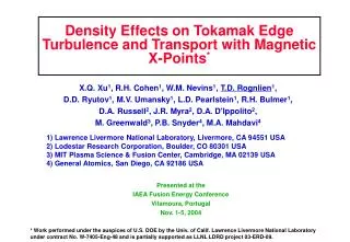
Density Effects on Tokamak Edge Turbulence and Transport with Magnetic X-Points* X.Q. Xu1, R.H. Cohen1, W.M. Nevins1, T.D. Rognlien1, D.D. Ryutov1, M.V. Umansky1, L.D. Pearlstein1, R.H. Bulmer1, D.A. Russell2, J.R. Myra2, D.A. D'Ippolito2, M. Greenwald3, P.B. Snyder4, M.A. Mahdavi4 1) Lawrence Livermore National Laboratory, Livermore, CA 94551 USA 2) Lodestar Research Corporation, Boulder, CO 80301 USA 3) MIT Plasma Science & Fusion Center, Cambridge, MA 02139 USA 4) General Atomics, San Diego, CA 92186 USA Presented at the IAEA Fusion Energy Conference Vilamoura, Portugal Nov. 1-5, 2004 * Work performed under the auspices of U.S. DOE by the Univ. of Calif. Lawrence Livermore National Laboratory under contract No. W-7405-Eng-48 and is partially supported as LLNL LDRD project 03-ERD-09.
Goal: understand role of edge-plasmas on limiting high-density operation • High density can increase fusion power (Pfus): Pfus n2 <v> • Tokamaks usually disrupt when the Greenwald limit is exceeded • 1- current profile shrinkage 2 MHD instability 3 disruption • Greenwald empirical scaling nG = Ip/a2 • higher density with central peaking implies an edge limit
Our turbulence/transport simulations provide details of an edge-plasma collapse ==> current profile shrinkage Goal: understand role of edge-plasmas on limiting high-density operation • High density can increase fusion power (Pfus): Pfus n2 <v> • Tokamaks usually disrupt when the Greenwald limit is exceeded • 1- current profile shrinkage 2 MHD instability 3 disruption • Greenwald empirical scaling nG = Ip/a2 • higher density with central peaking implies an edge limit
We have progressively improved edge turbulence and transport models together with basic understanding Turbulence model is 3D BOUT code • Braginskii --- collisional, two-fluids • full X-point geo. with separatrix • electromagnetic with A|| • Turbulence behavior with density • turbulence for fixed densities • short-time profile evolution • plasma “blob” formation and dynamics • Long-time transport effects • coupling BOUT to 2D UEDGE for wall recycled neutrals • role of impurity radiation • X-point & divertor leg effects • X-point shear decorrelation • a new beta-dependent divertor instability
c) 1.12xNG b) 0.58xNG a) 0.28xNG Saturated fluctuations for 3 densities:high collisionality drives turbulent transportup& parallel correlation down • Base-case (a): radial ni and Te,i profiles from DIII-D expt. tanh fit • Two other cases (b,c) with 2x and 4x density together with 0.5x and 0.25x temperatures
Largeperpendicular turbulence transport can exceed parallel transport at high density • D as n , D exhibits a nonlinear increase with n strong-transport boundary crossed • Large turbulence reduces Er shear layer allowing large transport to extend inwards
Numerous simulations varying density, Ip, and Bt show strong turbulence consistent with experimental limits • P0 = n0T0 held fixed while n0 changes • q held fixed while Ip changes • No change w/ Bt while Ip is fixed • Transport coefficients measured at separatrix • Greenwald Limit: nG=Ip/a2
8 6 Poloidal distance (cm) 4 2 0 -2 0 2 x (cm) Profile-evolving simulation shows generation and convection of plasma “blobs” as density increases ni [x,y,t] (1019 m-3) • Ion density evolved for ~1 ms from ionization of neutral source • Neutral density has spatial form nn= n0 exp(x/xw); xw = (icx)1/2; mimics wall recycling • Turbulence develops stronger ballooning character with blobs -0.6 0.0 0.6 1.2 1.8 2.4 3.0 Separatrix DIII-D
8 3.0 4 2.0 1.0 0 0. -0.5 Profile-evolving simulation shows generation and convection of plasma “blobs” as density increases ni [x,y,t] - ni[t=0] (1019 m-3) Poloidal distance (cm) 0.86 ms 1.06 ms DIII-D 0.69 ms -2 0 2 x (cm) • Analytic neutral model provides source for density build=up over ~1 ms • Rapid convective transport to wall at higher densities Density (1019 m-3) 1.22 ms 1.17 ms
Vorticity as density blob (contours) passes 4 (m) (+d) 1 (+d) Poloidial y (cm) 0 Vorticity(MHz) (-d) 0 20 10 Time (s) (-d) -4 0 1 2 3 Radial distance from sep. (cm) Characteristics of localized, intermittent “blobs” determined from detailed diagnostics of simulation data • 3D turbulence in realistic X-point geometry generates edge blobs • Higher density results in stronger turbulence giving robust blobs • Vorticity: = 2 • Example shows blobs spinning with monopole vorticity (m), which decays, allowing convective dipole vorticity (+d,-d) to develop Spatial history for 1 blob Convecting blob Spinning blob
- - - - - Electron B E ExB/B2 Ion B Perpend. charge transport; X-point shear Parallel charge transport Curvature charge separation + + + + + Regimes of blob edge-plasma transport understood through analytic analysis See Poster TH/P6-2, D. A. D’Ippolito, et al., Friday, 16:30 Current continuity eqn: J = 0 becomes • Analysis identifies parallel resistivity & X-point magnetic shear as key in blob velocity vs size, a • Sheath-connected: Vr ~ a-2 • X-point J: Vr ~ a-1/3 • And others, …
fluxes BOUT UEDGE Coupling iteration index is m profiles Turbulence Transport For long recycling timescales, we have coupled self-consistent edge turbulence/transport simulations • Density profile converges more rapidly than turbulent fluxes a) Midplane density profile evolution b) Midplane diffusion coeff. evolution
a) Constant D model a) Constant D model b) Coupled result b) Coupled result Results show that strong spatial dependence of transport substantially changes SOL and neutral distribution Effective diffusion coefficient Neutral density distribution • Poloidal variation understood from curvature instability • Wall flux and recycling modifies midplane neutrals
2D transport modeling shows that large radial convection can lead to an X-point MARFE • Mimic strong BOUT transport in UEDGE by a ballooning convective velocity varying from 0 to 300 m/s btwn. sep. & wall • Compare no convection and strong convections cases • Particle recycling and energy loss to radial wall included • Stronger neutral penetration increases density and impurity radiation loss - higher resistivity Self-consistent impurity transport still needed
Poloidal/parallel spatial correlation divertor reference Poloidal/parallel spatial correlation midplane reference Analysis of simulation shows decorrelation of turbulence between the midplane and divertor leg Cross-correlations of BOUT data by GKV analysis package shows decorrelation by X-point magnetic shear
Unstable mode effectively does not reach X-point if growth rate is large enough, Im > vA/L Instability is absent if no plate tilt and increases for larger outward tilt Localized mode exists (Im > 1) only if plasma beta high enough The mode reduces the divertor heat load without having direct impact on the main SOL Te New divertor-leg instability driven at “high” plasma-beta (density) by a radial tilt of the divertor plate. ~ ~
Summary and ongoing work We are working to: • Couple Er for long-time turbulence/transport evolution • Include self-consistent impurities • Enhance expt. comparisons • Simulate divertor-leg instability • Develop a 5D kinetic edge code • Increasing edge density (or collisionality) in X-point geometry • drives increasing turbulence that becomes very large “near” nGW • generates robust blobs • strong radial transport hastens edge cooling (neutrals, impurities) • X-point magnetic shear • causes decorrelation between midplane and divertor leg, large k • modifies blob dynamics as well as resistive instabilities • Plate (outward) tilt yields new finite-beta divertor instability