Optical Burst/Packet Switching Networks ( Based on the Application Packet Switching in Future
Optical Burst/Packet Switching Networks ( Based on the Application Packet Switching in Future

Optical Burst/Packet Switching Networks ( Based on the Application Packet Switching in Future
E N D
Presentation Transcript
Optical Burst/Packet Switching Networks(Based on the Application Packet Switching in Future Communication Networks) October 27, 2011 Nitu BaruaM.Sc. In Telematics, NTNU
Optical Packet Switching • A major adavntage of electronic packet switching is its bandwidth efficiency and ability to support diverse services. • Whcih packet switching concept into the optical domain, this is called optical packet switching(OPS). • For medium-term network scenarios, OPS using electronic control and header processing is more realistic.
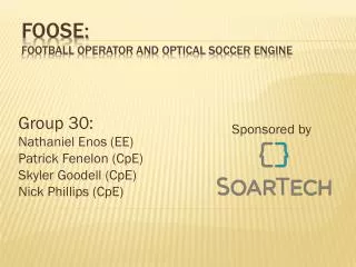
Application Fig 1. Applications of OPS as core and edge routers • A network comprising optical cross-connects(OXC) and OPS elements. • Resources can be used in a number of ways.. • For example, some optical channels (wavelength paths) may inteconnect high-capacity points that will fully utilized channel capacity, such as SDH (synchronous digital hierarchy) rings. • Other channels might be used to support optical packet transmission for efficient use of bandwidth, to either optimize resource utilization within the network.
There are mainly two application: 1. The application as a core switch. • Packet travelling trough the network undergo switching at core nodes where ongoing route selection and label swapping take place. -OPS maximizes utilization of the network resources. -Minimizingthe total network capacity required. - Reducing the size of the OXCs. 2. An edge router interfacing the electronic IP domain to the OTN(Optical Transport Network). -OPS provides a number of key functions required of the future OTN.
Control Planes • The entire traffic on any optical channel at an input port in an OXC is switched to an output port -the optical channel supports continuous data • IP traffic can not constructed as continous data streams. • Data/IP services are provided through networks that may include three or four different electronic multiplexing and switching layers -IP, Frame relay, ATM, SONET. • Optical data networking is the implementation of a network control plane, based on distributed label-switched management principles -the multiprotocol label switching (MPLS) control model. - and associated with the OXC.
The function of this control plane: -Initially be to establish - maintain optical paths within the network - and in the long term to determine -distribute and maintain state information associated with the OTN. • MPLS can provide a uniform control plane strategy in order to reduce the complexity of managing dissimilar networking systems.
The optical packet switch as Edge router and Aggregator • Fast switching and packet traffic aggregation for efficient bandwidth utilization will mainly be performed at the edge of the network. -the interface with the IP/ATM domain. -dynamic and fast wavelength allocation for packet traffic will be required. • Under this scenario, the OPS router will be an edge network device -which will function as a topological and logical interface between the service and transport layers.
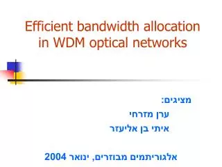
Fig 2.Interfacing of the OPS with the OXC • The OPS router can directly interface with the OXC • -which will make a set of static wavelength and fiber routes • available to the OPS traffic • An OXC making up a central switch fabric capable of interconnecting • the demultiplexed input wavelength channels to the appropriate outgoing fibers.
Interconnection is controlled through the management and control subsystems. • The OPS is positioned in the add-drop ports of the OXC and accesses wavelength channels dedicated to packet switching.
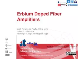
Fig 3. OPS functionality as an edge aggregator/router • The OPS will provide an aggregation mechanism in the external OTN nodes that can accept packet type transport from a number of sources and map onto optical packets • -IP and ATM • The aggregating nodes will then map the optical packet onto appropriate wavelengths for transport over the OTN to deaggregating nodes
That can either be egress points from the network or intermediary nodes that further map the opticak packets onto new wavelength paths. • During this process, the OPS will run a protocol capable of discovering the OXC network topology • And thus will be able to combine aggregation with quality of service (QoS) provisioning within the OTN.
Realization Issues To find the overall optimum packet transport solution for the optical edge aggregator, a number of issues need consideration: 1.The optical packet 2.Buffer memory implementation 3.Scheduling and control 4.Switch implementation
1.The optical packet • In order to reduce the number of entities that the switch must process per unit time, single or multiple packets with the same destination and quality of service class may be grouped together forming an optical packet at the edge of the network. • The optical packet will be of variable length, which will be integral multiple of a unit length. - it reduces the complexity of the packet switches. - it increase the complexity of the interface at the edge of the network.
2.Buffer memory implementation • To preserve an all-optical data path, it would be desirable to implement the buffer memeory in the IPS optically. • Optical memory is in a relatively primitive state; there is no such thing as optical random access memory (RAM) and it is necessary to resort to fiber delay lines for memory. • If these become unduly long (tens or hundreds of kilometers), they become very costly, bulky, and difficult to stabilize with respect to temperature.
Here, a compromise is proposed where electronics and optics share the buffering. -optics is used for very short delays, which form the vast majority of storage. -electronics is used for longer delays. • If a packet must be delayed more than the longest optical delay, it is passed to the electric memory.
Example: Optical delays line buffering handle all optical delays of 6750 bytes or less (i.e., a maximum fiber length of 1.08 km at 10 Gb/s); - then, on average, only 10 percent of the bytes in memory at any time are experiencing a larger delay, -are buffered in electronic memory • If the maximum optical delay is increased to 11,500 bytes, this corresponds to a maximum fiber length of 1.84 km and only 1 percent of bytes in electronic memory.
3. Scheduling and control • Optical memory is implemented with delay lines and not RAM, the electronic scheduler for the architecture must direct the packets over the correct delay lines to make the architecture perform the same function as one constructed from RAM buffers. • The packet scheduling algorithms for the transport solutions can be implemented using high-speed electronics, and must consider issues such as - fairness - implementation of QoS classes - queue stability and - queue starvation
Due to the bulkiness and expense of large amounts of delay line fiber, two techniques may be used to reduce the total length of fiber required; This impacts upon the control algorithm: • Multiple packets on different wavelengths may pass along a specific delay path simultaneously. • The total length of fiber delay line memory can also be reduced by sharing fibers between different delay paths.
Fig. 4. a) The probability that a randomly chosen byte is experiencing adelay greater than the given value in an output-buffered switch, for self-similar traffic, with a mean traffic level of 80 percent; b and c) an example of sharing delay lines. The subsystem in b) requires 5 m of fiber delay line, whereas only 3 m are required in c), because the smallest delay line has been moved in front of the splitter.
In above fig. 4 Shows that, it can be extended so that a large array of fiber delays can be replaced by multiple delay line stages, with a dramatic reduction in the amount of fiber required.
4. Switch implementation • A generic structure of the proposed packet switch consists of an input processing interface, a switching and buffering block, and an output processing module. Fig 5. a) A schematic diagram of the generic structure of the optical packet switch; b) concatenation performance of the wavelength converter and AWG arrangement; back-to-back measurement shown for comparison
The input interface performs delineation (i.e., identification of the packet start and end), packet format adaptation into the optical packet, classification into forward equivalent classes defined for the OTN and electronic buffering. • The switching and buffering blocks are responsible for the routing of the optical packets to the appropriate output ports and contention resulation respectively, • While output interface is responsible for header reinsertion and per packet conditioning such as - wavelength conversion to the appropriate OTN wavelengths, - regeneration and - power equalization
In fig 5b shows that measured Q factor for both back- to-back and system (i.e., AWG and wavelength converter) configuration. AWG is arrayed waveguide grating. • This results demonstrate penalty-free operation for up to 25 cascaded nodes.