Chapter 10 cont.
Dimensioning and Tolerancing. Chapter 10 cont. Dimensioning Features (cont.) Hexagons and polygons. Should be dimensioned across the flats in a view that shows it in it’s true shape. Arcs. Dimensioned with a leader in a view where shown as it’s true shape
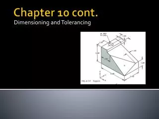

Chapter 10 cont.
E N D
Presentation Transcript
Dimensioning and Tolerancing Chapter 10 cont.
Dimensioning Features (cont.)Hexagons and polygons • Should be dimensioned across the flats in a view that shows it in it’s true shape
Arcs • Dimensioned with a leader in a view where shown as it’s true shape • Diameters-dimensioned with symbol before the value • Radii-dimensioned with capitol R before the value • Leader should theoretically extend through the center of the arc • Leader can physically extend through the center of the arc to help locate the arc center
Center Marks • Center marks should be placed on all diameter features • Center marks should only be placed on radii that require center location
Spherical features • Spherical radii dimensioned with an SR before dim value • Spherical Diameters dimensioned with an S before the dim value
Contours • Shapes that are not defined as arcs • Dimensioned by locating points along the contour
Locating a Point • Method of locating points that are not part geometry but are necessary to describe the shape • Commonly referred to as “point of intersection” or PI PI Often PI will be used to note point of intersection
Notes for size featuresHoles Holes-dimensioned in views where they appear as circles or in a sectional view
Dimensioning blind holes • Blind holes-a hole that does not go thru the part • Depth must be given in one of two ways
Counterbore • One small thru hole for a fastener to pass through • One large hole to recess the head of a fastener below the surface of the part
You will need to know how to place one style of these notes on a drawing
Countersink • One small thru hole for a fastener to pass through • Large hole has angled sides to accept a countersink headed fastener • Fastener head sits flush with top of the part
You will need to know how to place one style of these notes on a drawing
Counterdrill • Combination counterbore and countersink You will need to know how to place one style of these notes on a drawing
Spotface • Similar to a counterbore accept for the depth of the large hole • Large hole is a machined surface to provide a flat bearing surface for a fastener to clamp against • Depth is determined by machinist based on how rough the surface of the part is • Seen commonly on cast parts
You will need to know how to place one style of these notes on a drawing
Slotted Holes • Must define length and width (and location) • Choose a method based on what is important for part function
Knurls • A pattern machined into parts to provide grip • Not shown in true detail on drawings • Defined by a note with a leader to show the area to be knurled
Necks and grooves • Areas on cylindrical parts where the diameter changes for a certain length • Appear on turned parts
Repetitive Features • When a part has more than one feature of the same size, they can be dimensioned with a note that specifies the number of features • Should only be used when it is obvious which features are the same size