Download
1 / 43
540 likes | 1.22k Vues
Physical Impairments in Optical Systems and Networks (FIBER NON-LINEARITIES). Prof. Manoj Kumar Dept. of Electronics and Communication Engineering DAVIET Jalandhar. Outline. Problems posed by Chromatic Dispersion Problems posed by Fiber Nonlinearities Possible Solutions

E N D
Physical Impairments in Optical Systems and Networks(FIBER NON-LINEARITIES) Prof. Manoj Kumar Dept. of Electronics and Communication Engineering DAVIET Jalandhar
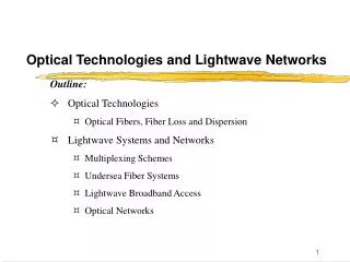
Outline • Problems posed by Chromatic Dispersion • Problems posed by Fiber Nonlinearities • Possible Solutions • Practical Issues
Transmission Impairments 2.5 “Optical Windows” 4 5 2 3 AllWaveTM eliminates the 1385nm water peak 2.0 OH Absorption 1 1.5 Attenuation (dB/km) 1.0 0.5 1100 1300 900 1500 1700 Wavelength (nm) Main cause of attenuation: Rayleigh scattering in the fiber core
EDFA + Raman Amplifier EDFA 1.8 Gb/s 405 Mb/s 810 Mb/s TDM DWDM Bandwidth Evolutionary Landmarks All-Optical Network (Terabits Petabits) TDM (Gb/s) 80l @ 40Gb/s 40 176l @OC-192 40 Gb/s 35 Enablers EDFA + Raman Amplifier Dense WDM/Filter High Speed Opto-electronics Advanced Fiber 32l @OC-192 30 16l @OC-192 25 Bandwidth 8l @OC-48 4l @OC-192 20 15 10 Gb/s 10 2l @1.2Gb/s (1310 nm, 1550 nm) 4l @OC-48 5 2l @OC-48 1.2 Gb/s 565 Mb/s 2.4 Gb/s 0 2006 2004 1992 1998 2000 1982 1984 1986 1988 1990 1994 1996 2002
Multiplexing • Two ways to increase transmission capacity: • Increase the bit rate • WDM: wavelength division multiplexing • High speed electronics, TDM & OTDM • 32 at 2.5 Gbit/s on 1 fiber (or less at 10Gbit/s)
Switch Traffic with Higher Granularity Significantly Reduce the Cost per Byte Wavelength Routed Optical Networks Cost-Effective Control Architecture of WDM Optical Networks Explosive Growth of Internet Traffic ?
Faster Electronics Electronics more expensive Fiber Compatibility Fiber Capacity Release Fast Time to Market Lower Cost of Ownership Utilizes existing TDM Equipment Wavelength Division Multiplexing Slow Time to Market Expensive Engineering Limited Rights of Way Duct Exhaust More Fibers WDM Drivers
Wavelength Converter 1 Wavelength Converter 1 Wavelength Converter 2 Wavelength Converter 2 Mux &Demux Mux &Demux Wavelength Converter n Wavelength Converter n Ch n Ch 2 Ch 1 WDM System Function
Design Parameters of WDM Network • Number of Wavelengths • Bit Rate per Wavelength • Channel Spacing • Useable Bandwidth • Bandwidth Efficiency • Span between Optical Amplifiers • Transmission Span without Regeneration
Problem Posed by Chromatic Dispersion • Chromatic Dispersion • Non-zero 2 at 1550nm (D=17ps/nm-km) • Different frequencies travel at different group velocities • Results in pulse broadening causing ISI • Sources of chromatic dispersion • Finite Laser line-width • Laser Chirp due to direct modulation • Finite Bandwidth of the bit sequence
Chromatic Dispersion (CD) Effect and consequences • The refractive index has a wavelength dependent factor, so the different frequency-components of the optical pulses are travelling at different speeds (the higher frequencies travel faster than the lower frequencies) • The resulting effect is a broadening of the optical pulses and a consequent interference between these broadened pulses Counteractions CD compensation, Use of DS or NZDS fibres, combinations of these two techniques
SMF, DSF, NZDSF • SMF : Single Mode Fiber covered by ITU-T G.652 Recommendation • DSF : Dispersion Shifted Fiber covered by ITU-T G.653 Recommendation • NZDSF : Non-Zero Dispersion Shifted Fiber covered by ITU-T G.655 Recommendation
Chromatic Dispersion (CD) • The dispersion paradigm : Even if it is important to reduce Chromatic Dispersion in order to achieve longer transmission distances ... HOWEVER ... too little dispersion means too high non-linear effects in the transmission fiber that can severely degrades Bit Error Ratio (BER)
Fiber Nonlinearities • As long as optical power within an optical fiber is small, the fiber can be treated as a linear medium; that is the loss and refractive index are independent of the signal power • When optical power level gets fairly high, the fiber becomes a nonlinear medium; that is the loss and refractive index depend on the optical power
Limitations :short list of fibre nonlinearities Single-channel Multi-Channel/WDM Kerr effect P(t) n = n(w) + n2 Aeff Self-phase modulation (SPM) signal optical phase modulated proportionally to signal power; conversion to intensity «noise» by GVD. Cross-phase modulation (XPM) Signal optical phase modulated proportionally to power of neighboring channels; conversion to intensity «noise» by GVD. Modulation instability (MI) (anomalous dispersion regime only) selective amplification of noise. Four-wave mixing (FWM) Generation of new spectral components; crosstalk when overlap with other channels. Other interactions with medium Stimulated Brillouin scattering (SBS) Retrodiffusion of energy; increases fibre loss. Stimulated Raman scattering (SRS) Energy transfer from lower-wavelength channels to higher-wavelength ones.
Transmission Fiber f f Stimulated Raman Scattering (SRS) 1) Effect and consequences • SRS causes a signal wavelength to behave as a “pump” for longer wavelengths, either other signal channels or spontaneously scattered Raman-shifted light. The shorter wavelengths is attenuated by this process, which amplifies longer wavelengths • SRS takes place in the transmission fiber 2) SRS could be exploited as an advantage • By using suitable Raman Pumps it is possible to implement a Distributed Raman Amplifier into the transmission fiber. This helps the amplification of the signal (in co-operation with the localized EDFA). The pumps are depleted and the power is transferred to the signal
Non Linear Effects:Cross Phase Modulation (XPM) • XPM acts as a crosstalk penalty, which increases with increasing channel power level and system length and with decreasing channel spacing • XPM causes a spectral broadening of the optical pulses and thus reduces the dispersion tolerance of the system • At 10 Gbps, its penalty is minimized by distributing dispersion compensation at each line amplifier site • If dispersion is compensated only at the terminal ends, there will be a residual penalty due to XPM
FIBER EFFECTIVE LENGTH • Nonlinear interaction depends on transmission length and cross-sectional area of the fiber • The longer the length, the more the interaction and the worse the effect of the nonlinearity. • BUT, signal propagates along link and experiences loss (from fiber attenuation) … • ...complicated to model. Simple model: Assume power is constant over a certain effective length P denotes power transmitted into fiber. L denotes actual fiber length P(z) = P e-az power at distance z along link. Typical: a = 0.22 dB/km at 1.55um if L>>1/ a ,then Le approx 20 km
EFFECTIVE CROSS SECTIONAL AREA Effect of nonlinearity grows with intensity in the fiber. This is inversely proportional to the area of the core (for a given power). Power not evenly distributed in the cross section. Use effective cross sectional area (for convenience). A = actual cross sectional area I(r, q) = actual cross sectional distribution of the intensity. Most cases of interest:
SBS • The phonons are acoustic phonons. • Pump and Stokes wave propagate in opposite directions. • Does not typically cause interaction between different wavelengths. • Creates distortion in a single channel. • Depletes the transmitted signal. • The opposite traveling Stokes wave means the transmitter needs an isolator Meaning: If we launched 1.05mW = 0.2dBm, fiber loss alone would cause the receiver to receive 0.2dBm-(0.2dB/km)(20km) = -3.8dBm. However, if SBS is present, the Stokes and signal powers are equal in threshold condition; therefore the receiver gets -3.8dBm- 3dB = -6.8 dBm. The backwards Stokes wave has power of -6.8 dBm.
SRS • If two or more signals at different wavelengths are injected into a fiber, SRS causes • power to be transferred from the lower wavelength channels to the higher-wavelength • channels. • Has a broadband effect (unlike SBS) • Gain coefficient gR much less than SBS gain coefficient gB. • Both forward and reverse traveling Stokes wave. • Coupling between channels occurs only if both channels sending a “1”. SRS penalty • is therefore reduced by dispersion. SRS generally does not contribute to fiber systems.
Non Linear Effects:Four Wave Mixing (FWM) 1) Effect and consequences • FWM is the generation of new optical waves (at frequencies which are the mixing products of the originator signals). This is due to interaction of the transmitted optical waves. The created mixing products interfere with the signal channels causing consequent eye closing and BER degradation Decreasing channel spacingand chromatic dispersion will increase FWM • N channels N2(N-1)/2 side bands are created, causing • Reduction of signals • Interference • Cross talk 2) Counteractions • Avoid use of ITU-T G.653 (DSF) fiber, Use of ITU-T G.652 (SMF) fiber and ITU-T G.655 (NZDSF) fiber • Unequal channel spacing will cause the mixing products to be created at different frequencies which do not interfere with the signal channels
Non Linear Effects:Four Wave Mixing (FWM) cont… • Consider a simple three wavelength (l1, l2 & l3) • Let’s assume that the input wavelengths are ll = 1551.72 nm, l2 = 1552.52 nm & l3 = 1553.32 nm. The interfering wavelengths that are of most concern in our hypothetical three wavelength system are: • l1 + l2 - l3 = 1550.92 nm • l1 - l2 + l3 = 1552.52 nm • l2 + l3 . l1 = 1554.12 nm • 2l1 - l2 = 1550.92 nm • 2l1 - l3 = 1550.12 nm • 2l2 - l1 = 1553.32 nm • 2l2 - l3 = 1551.72 nm • 2l3 - l1 = 1554.92 nm • 2l3 - l2 = 1554.12 nm
Critical Issues • Receiver Sensitivity (Minimum Power @ RX) • Fiber Chromatic Dispersion • Fiber PMD • Non-linear Effects • Mode partition Noise
Mode partition Noise • Mode Partition Noise is a problem in single mode fiber operation • The problem is that fiber dispersion varies with wavelength. • With changes in the wavelength of the laser, the group velocity also changes. • Thus instead of getting an even dispersion as we might if all wavelengths were produced simultaneously, we get random and unpredictable variations in the received signal strength – even during a single bit time • This is a form of noise and degrades the quality of the received signal
Polarization-Mode Dispersion • Singlemode actually has two orthogonal components • Real fiber is not completely symmetric • Recall geometry data in sheets • Components propagate at different velocities • Thus, another form of dispersion (PMD) • Small, but significant when other forms of dispersion are suppressed
Polarizations of fundamental mode Two polarization states exist in the fundamental mode in a single mode fiber
Polarization Mode Dispersion (PMD) Each polarization state has a different velocity PMD
PMD Pulse Spreading • DPMD does not depend on wavelength • Typical value: 0.5 pskm • Therefore, 5 ps for a 100 km fiber
Bit Rate of Singlemode Fiber • Recall the bit rate formula • For chromatic dispersion • For polarization-mode dispersion
Dispersion compensation techniques • Postcompensation • Precompensation • Hybrid/Symmetrical Compensation • Optical Equalization Filters • Optical Phase Conjugation • Fiber Bragg gratings • Dispersion Compensation Fibers
Tools to combat Impairments • Power per Channel • Dispersion Compensation • Channel Spacing • Wavelength or Frequency Choice
Initial configuration Limitations: - Technology - Physical effects within line fiber Bandwidth Btot Per channel bit rate: R Channel spacing: Dl Dl Wavelength Upgrade strategies: B’tot, R’, Dl’ - Higher-speed electronics required - Polarization mode dispersion (PMD) group-velocity dispersion (GVD) self-phase modulation (SPM) - increase in the per channel bit rate R’ > R B’tot = Btot and Dl’ = Dl - decrease in the channel spacing Wavelength Dl’ < Dl B’tot = Btot and R’ = R - increase in the total WDM bandwidth Wavelength - Broadband amplifiers - WDM nonlinearity (Raman) B’tot > Btot with Dl’ = Dl and R’ = R + higher channel count Wavelength Increasing Total Throughput of WDM Systems - Channel selection and stabilization multiplexing / demultiplexing - WDM nonlinearities (FWM, XPM, Raman)
Fixed connectivity (in a first step) 10-Gbit/s switch 10-Gbit/s switch 40-G aggr. 40-G transp. 40-G transp. 40-G aggr. 40-G aggr. 40-G transp. 40-G transp. 40-G aggr. 9.95-Gbit/s tributary 9.95-Gbit/s tributary WDM WDM IP IP 10-Gbit/s trib. 10-Gbit/s trib. 10G TRIB 40-Gbit/s point-to-point topology Up to 40 Up to 40 ATM ATM SDH ADM SDH ADM Other Other IP IP Capacity Increase via Increase inPer-Channel Bit Rate: 40-Gbit/s Channel • Scalable, transparent, flexible and cost-optimized access tothe backbone: • 40-Gbits/s system as a tributary of the Alcatel WDM platforms • NO management of STM-256 framing and synchronization • transparent 4:1 concentration of 10-Gbit/s plesiochronous sources • embedded scalable 10Gbit/s OXC connectivity • flexible bandwidth optimization and network protection