Download
1 / 31
310 likes | 387 Vues
Learn basic drawing techniques using commands like LINE, XLINE, RAY, PLINE, and RECTANG in technical drawing. Understand Cartesian, Polar, and Relative coordinates to create shapes efficiently. Practice drawing squares, rectangles, arrows, and more.

E N D
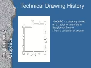
Technical Drawing – Week 2 2008-Fall
Drawing Simple Objects • Command Promt • Draw Menu • Draw Toolbox
Line • Command: LINE • Specify first point: (pick P1) • Specify next point or [Undo]: (pick P2) • Specify next point or [Undo]: (to end)
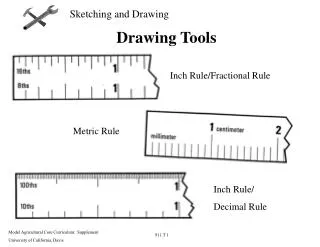
Picking Points • Mouse • Absolute Coordinates • Cartesian Co-ordinates • Polar Co-ordinates • Relative Coordinates • Cartesian Co-ordinates • Polar Co-ordinates • Object Snapping (future)
Picking Points • Absolute Coordinates • Cartesian Co-ordinates • Polar Co-ordinates
Picking Points • Relative Coordinates previous point as (0,0) • Command Sequence • Command: LINE • From point: 30,40 (an absolute Cartesian co-ordinate) • To point: @0,12 (a relative Cartesian co-ordinate) • To point: @12<0 (a relative polar co-ordinate) • To point: @0,-12 (another relative Cartesian co-ordinate) • To point: C (to close) • Try this sequence out and watch the square drawn as you enter each co-ordinate value. You can also use this method to quickly draw a rectangle of known size. Say you needed to draw a rectangle 20 drawing units wide and 10 drawing units high and you didn't mind where exactly the rectangle is drawn, you could do this: • Command Sequence • Command: RECTANGLE • Specify first corner point or [Chamfer/Elevation/Fillet/Thickness/Width]: (pick a point near the middle of the drawing area) • Specify other corner point or [Dimensions]: @20,10
Exercise • Draw the following arrow using Cartesian co-ordinates
Exercise • Draw the following shape using Polar co-ordinates
The Construction Line Command • Keyboard XLINE, short-cut XL • Infinitely long lines passing through two specified points. • Construction lines are not normally used as objects in finished drawings, it is usual, therefore, to draw all your construction lines on a separate layer which will be turned off or frozen prior to printing. • You may notice that there are a number of options with this command. For example, the "Hor" and "Ver" options can be used to draw construction lines that are truly horizontal or vertical. In both these cases, only a single pick point is required because the direction of the line is predetermined. To use a command option, simply enter the capitalised part of the option name at the command prompt. Follow the command sequence below to see how you would draw a construction line using the Horizontal option. • Command Sequence • Command: XLINE • Hor/Ver/Ang/Bisect/Offset/<From point>: H • Through point: (pick a point to position the line) • Through point: (to end or pick a point for another horizontal line)
The Ray Command • Keyboard RAY • The Ray command creates a line similar to a construction line except that it extends infinitely in only one direction from the first pick point. The direction of the Ray is determined by the position of the second pick point. • Command Sequence • Command: RAY • Specify start point: (pick the start point) • Specify through point: (pick a second point to determine direction) • Specify through point: (to end or pick another point)
The Polyline Family • Polylines differ from lines in that they are more complex objects. A single polyline can be composed of a number of straight-line or arc segments. Polylines can also be given line widths to make them appear solid. The illustration below shows a number of polylines to give you an idea of the flexibility of this type of line. • Polylines can be edited after they are created to, for example, change their width. You can do this using the PEDIT command, ModifyObjectPolyline from the pull-down menu.
The Polyline Command • The Polyline or Pline command is similar to the line command except that the resulting object may be composed of a number of segments which form a single object. In addition to the two ends a polyline is said to have vertices (singular vertex) where intermediate line segments join.Just hit to end. As with the Line command, you also have the option to automatically close a polyline end to end. To do this, type C to use the close option instead of hitting . • Command Sequence • Command: PLINE • Specify start point: (pick P1) • Current line-width is 0.0000 • Specify next point or [Arc/Halfwidth/Length/Undo/Width]: (pick P2) • Specify next point or [Arc/Close/Halfwidth/Length/Undo/Width]: (pick P3) • Specify next point or [Arc/Close/Halfwidth/Length/Undo/Width]: (pick P4) • Specify next point or [Arc/Close/Halfwidth/Length/Undo/Width]: (pick P5) • Specify next point or [Arc/Close/Halfwidth/Length/Undo/Width]: (or C to close)
The Rectangle Command • Keyboard RECTANGLE short-cuts REC, RECTANG • The Rectangle command is used to draw a rectangle whose sides are vertical and horizontal. It is, in fact, just a closed polyline which is automatically drawn for you. • Command Sequence • Command: RECTANG • Specify first corner point or [Chamfer/Elevation/Fillet/Thickness/Width]: (pick P1) • Specify other corner point or [Dimensions]: (pick P2) • Has a number of options. • Width works in the same way as for the Polyline command. • The Chamfer and Fillet see the Modifying Objects tutorial for details. • Elevation and Thickness are 3D options. • Instead of picking a second point to draw the rectangle, you have the option of entering dimensions: • Command Sequence • Command: RECTANG • Specify first corner point or [Chamfer/Elevation/Fillet/Thickness/Width]: (pick a point) • Specify other corner point or [Dimensions]: D • Specify length for rectangles <0.0000>: 20 • Specify width for rectangles <0.0000>: 10 • Specify other corner point or [Dimensions]: (pick a point to fix the orientation)
The Polygon Command • Keyboard POLYGON, short-cut POL • Command Sequence • Command: POLYGON • Enter number of sides <4>: 5 • Specify center of polygon or [Edge]: (pick P1 or type E to define by edge length) • Enter an option [Inscribed in circle/Circumscribed about circle] <I>: (to accept the inscribed default or type C for circumscribed) • Specify radius of circle: (pick P2 or enter exact radius)
The Donut Command • Keyboard DONUT short-cut DO • Command Sequence • Command: DONUT • Specify inside diameter of donut <0.5000>: (pick any two points to define a diameter or enter the exact length) • Specify outside diameter of donut <1.0000>: (pick any two points to define a diameter or enter the exact length) • Specify center of donut or <exit>: (pick P1) • Specify center of donut or <exit>: (to end or continue to pick for more doughnuts)
The Revcloud Command • Keyboard REVCLOUD • The Revcloud command is used to draw a "freehand" revision cloud or to convert any closed shape into a revision cloud. • Command Sequence • Command: REVCLOUD • Minimum arc length: 66.6377 Maximum arc length: 116.6159 • Specify start point or [Arc length/Object] <Object>: (Pick P1) • Guide crosshairs along cloud path... • Move the mouse to form a closed shape; the command automatically ends when a closed shape is formed. • You can use the "Arc length" option to control the scale of the revision cloud. This is achieved by specifying the minimum and maximum arc length. The "Object" option is used to transform any closed shape, such as a polyline, spline or circle into a revision cloud.
The 3D Polyline Command • Keyboard 3DPOLY • The 3D Polyline command works in exactly the same way as the Polyline command. The main difference between a normal polyline and a 3D polyline is that each vertex (pick point) of a 3D polyline can have a different value for Z (height). In normal (2D) polylines, all vertexes must have the same Z value. • 3D polyline objects are not as complex as their 2D cousins. For example, they cannot contain arc segments and they cannot be given widths. However, they can be very useful for 3D modeling. • Command Sequence • Command: 3DPOLY • Specify start point of polyline: (pick a point) • Specify endpoint of line or [Undo]: (pick another point) • Specify endpoint of line or [Undo]: (pick a third point) • Specify endpoint of line or [Close/Undo]: (to end, C to close or continue picking points) • Notice that you are not prompted for a Z value each time you pick a point. You must either use one of the Object Snaps to pick a point with the required Z value or use the ".XY" filter to force AutoCAD to prompt for a Z value.
The Circle Command • Keyboard CIRCLE, short-cut C • Various ways to draw a circle • Center + radius • Center + diameter • 2 points of diameter • 3 peripheral points • Tangent + tangent + radius • Tangent + tangent + tangent
The Arc Command • Keyboard ARC short-cut A • The Arc command allows you to draw an arc of a circle. There are numerous ways to define an arc, the default method uses three pick points, a start point, a second point and an end point. Using this method, the drawn arc will start at the first pick point, pass through the second point and end at the third point. Once you have mastered the default method try some of the others. You may, for example need to draw an arc with a specific radius. All of the Arc command options are available from the pull-down menu. • Command Sequence • Command: ARC • Specify start point of arc or [Center]: (pick P1) • Specify second point of arc or [Center/End]: (pick P2) • Specify end point of arc: (pick P3) • It is also possible to create an arc by trimming a circle object. In practice, many arcs are actually created this way. See the Trim command on the Modifying Objects tutorial for details.
The Spline Command • Keyboard SPLINE, short-cut SPL • The Spline command creates a type of spline known as a nonuniform rational B-spline, NURBS for short. A spline is a smooth curve that is fitted along a number of control points. • The Fit Tolerance option can be used to control how closely the spline conforms to the control points. • Command: SPLINE • Specify first point or [Object]: (Pick P1) • Specify next point: (Pick P2) • Specify next point or [Close/Fit tolerance] <start tangent>: (Pick P3) • Specify next point or [Close/Fit tolerance] <start tangent>: (Pick P4) • Specify next point or [Close/Fit tolerance] <start tangent>: • Specify start tangent: (pick a point) • Specify end tangent: (pick a point)
The Ellipse Command • Keyboard ELLIPSE, short-cut EL • The Ellipse command gives you a number of different creation options. The default option is to pick the two end points of an axis and then a third point to define the eccentricity of the ellipse. After you have mastered the default option, try out the others. • Command Sequence • Command: ELLIPSE • Specify axis endpoint of ellipse or [Arc/Center]: (pick P1) • Specify other endpoint of axis: (pick P2) • Specify distance to other axis or [Rotation]: (pick P3)
The Region Command • Keyboard REGION short-cut REG • A region is a surface created from objects that form a closed shape, known as a loop. The Region command is used to transform objects into regions rather than actually drawing them (i.e. you will need to draw the closed shape or loop first). Once a region is created, there may be little visual difference to the drawing. However, if you set the shade mode to "Flat Shaded", ViewShadeFlat Shaded, you will see that the region is, in fact, a surface and not simply an outline. Regions are particularly useful in 3D modeling because they can be extruded. • Before starting the Region command, draw a closed shape such as a rectangle, circle or any closed polyline or spline. • Command Sequence • Command: REGION • Select objects: (Pick P1) • Select objects: • 1 loop extracted. • 1 Region created. • You can use the boolean commands, Union, Subtract and Intersect to create complex regions
The Wipeout Command • Keyboard WIPEOUT • A Wipeout is an image type object. Most commonly it is used to "mask" part of a drawing for clarity. • Command Sequence • Command: WIPEOUT • Specify first point or [Frames/Polyline] <Polyline>: (Pick P1) • Specify next point: (Pick P2) • Specify next point or [Undo]: (Pick P3) • Specify next point or [Close/Undo]: (Pick P4) • Specify next point or [Close/Undo]: Frames ON Frames OFF
The Point Command • Keyboard POINT short-cut PO • The point command will insert a point marker in your drawing at a position which you pick in the drawing window or at any co-ordinate location which you enter at the keyboard. • Command Sequence • Command: POINT • Current point modes: PDMODE=0 PDSIZE=0.0000 • Specify a point: (pick any point) • The default point style is a simple dot, which is often difficult to see but you can change the point style to something more easily visible or elaborate using the point style dialogue box. • You can start the point style command from the keyboard by typing DDPTYPE or you can start it from the pull-down menu at Format Point Style… The command starts by displaying a dialogue box offering a number of options.
The Multiline Command • Keyboard MLINE short-cut ML • Command Sequence • Command: MLINE • Current settings: Justification = Top, Scale = 20.00, Style = STANDARD • Specify start point or [Justification/Scale/STyle]: (Pick P1) • Specify next point: (Pick P2) • Specify next point or [Undo]: (Pick P3) • Specify next point or [Close/Undo]: (to end or continue picking or C to close)
The Multiline Style Command • Pull-down FormatMultiline Style… • Keyboard MLSTYLE
The Multiline Style Command • Pull-down FormatMultiline Style… • Keyboard MLSTYLE
Tips & Tricks • You will have noticed that many of the draw commands require the key on the keyboard to be pressed to end them. In AutoCAD, clicking the right mouse key and selecting "Enter" from the context menu has the same effect as using the key on the keyboard. Using the right-click context menu is a much more efficient way of working than using the keyboard. • You can also use the key or right mouse click to repeat the last command used. When a command has ended, you can start it again by right clicking and selecting "Repeat command" from the context menu rather that entering the command at the keyboard or selecting it from the pull-down or toolbar. By this method it is possible, for example, to repeat the line command without specifically invoking it.
Tips & Tricks • The command sequence might be something like the one below. • Command Sequence • Command: LINE • Specify first point: (pick P1) • Specify next point or [Undo]: (pick P2) • Specify next point or [Undo]: (right-click and select Enter) • Command: (right-click and select Repeat Line) • Specify first point: (pick P1) • Specify next point or [Undo]: (pick P2) • Specify next point or [Undo]: (right-click and select Enter) • Command: (right-click and select Repeat Line)… • You could continue this cycle as long as you needed, using only the mouse for input. • You can change the Linetype of any of the objects created in the above tutorial. By default all lines are drawn with a linetype called "Continuous". This displays as a solid line. However, lines can be displayed with a dash, dash-dot and a whole range of variations. See the Object Properties tutorial for details.
Exercise • Do it yourself by using object drawing commands • Use a different layer for construction lines
Next Week • Modifying objects