Beamwidth Profiling Devices
Explore beam profiling devices for TRUS needle localization experiments. Set up with rubber membrane and nylon wires. Analyze beam profiles and side lobe effects. Compatible with commercial steppers.

Beamwidth Profiling Devices
E N D
Presentation Transcript
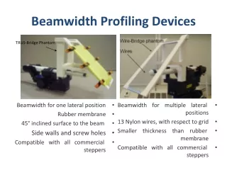
Beamwidth Profiling Devices TRUS-Bridge Phantom • Beamwidth for one lateral position • Rubber membrane • 45° inclined surface to the beam • Side walls and screw holes • Compatible with all commercial steppers • Beamwidth for multiple lateral positions • 13 Nylon wires, with respect to grid • Smaller thickness than rubber membrane • Compatible with all commercial steppers
Beam Profiling Experimental Setup • TRUS images acquired for every depth and manually segmented • Experimented with the SonixTouch US machine • US beam profile is generated
TRUS Beam Profile R=Rectum PZ= Peripheral Zone U=Urethra TZ=Transitional Zone TZ U PZ R • Section-thickness starts diverging after the focal zone • Focal zone is closely located to the US transducer Figure: http://www.keyholeurology.co.uk/prostatecancer.html
Needle Localization Measurement Needle localization of main beam Needle Localization of main and side lobe beams • Compare the observed reflections to a reference point • Ref. point=first inserted needle reflection on a column
Needle Insertion Experimental Setup • Brachytherapy stepper and grid template are in submerged distilled water-glycerol bath • Experimented with the SonixTouch US machine • For each needle, the stepper position where the first reflection appears is recorded
Needle Localization Offset • Average and std. of N(j)-N(1) for gain=0%, dynamic range= 15, 50 and 100 dB, and power=0,-4, and -7 • Beam converges to a point and diverges right after • Beam has a focal zone
Needle Localization Offset • Average and std. of N(j)-N(1) for gain=0%, dynamic range= 15, 50 and 100 dB, and power=0,-4, and -7 • Beam converges to a point and diverges right after • Beam has a focal zone
Side Lobe Effects Intensity profile of main beam Intensity profile of main and side lobe beams • Group of thin, parallel, low intensity bands on both sides corresponding to side lobes