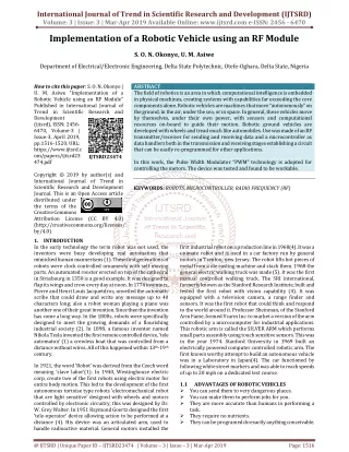
Wireless Remote using RF Module
With advanced technology, people try to avail wireless technologies in different roles. In this paper, the RF modules are implemented as modernized wireless system to overcome the use of wire. RF transmitter and RF receiver are main devices of the system. And then LED, transformer, relay, and push buttons are used as supporting components of the system. HT12E and HT12D are mainly used for decoding and encoding the data. The HT12E encoder IC converts the 4 bit data from the 4 data pins that are connected to buttons into serial data. This serial data is sent to RF transmitter. The RF transmitter transmits this serial data using signals. At the receiver side, the RF receiver receives the serial data. This serial data is sent to HT12D decoder IC which converts into 4 bit parallel data. The 4 data pins of decoder are connected to LEDs. According to the button pushed, the LEDs can be turned ON and OFF meaning that the specific task or function can be carried out by mean of remote predefined key. In today's world, there is a continuous need for wireless control using with transmitter and receiver in standard and modern living. Dr. Thida Aung "Wireless Remote using RF Module" Published in International Journal of Trend in Scientific Research and Development (ijtsrd), ISSN: 2456-6470, Volume-3 | Issue-5 , August 2019, URL: https://www.ijtsrd.com/papers/ijtsrd26780.pdf Paper URL: https://www.ijtsrd.com/engineering/electronics-and-communication-engineering/26780/wireless-remote-using-rf-module/dr-thida-aung<br>

Wireless Remote using RF Module
E N D
Presentation Transcript
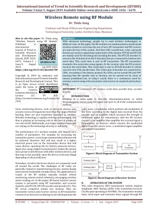
International Journal of Trend in Scientific Research and Development (IJTSRD) Volume 3 Issue 5, August 2019 Available Online: www.ijtsrd.com e-ISSN: 2456 – 6470 Wireless Remote using RF Module Dr. Thida Aung Professor and Head of Electronic Engineering Department, Technological University, Lashio, Northern Shan, Myanmar How to cite this paper: Dr. Thida Aung "Wireless Remote using RF Module" Published in International Journal of Trend in Scientific Research and Development (ijtsrd), ISSN: 2456- 6470, Volume-3 | Issue-5, August 2019, https://doi.org/10.31142/ijtsrd26780 Copyright © 2019 by author(s) and International Journal of Trend in Scientific Research and Development Journal. This is an Open Access article distributed under the terms of the Creative Commons Attribution License (CC (http://creativecommons.org/licenses/by /4.0) ABSTRACT With advanced technology, people try to avail wireless technologies in different roles. In this paper, the RF modules are implemented as modernized wireless system to overcome the use of wire. RF transmitter and RF receiver are main devices of the system. And then LED, transformer, relay, and push buttons are used as supporting components of the system. HT12E and HT12D are mainly used for decoding and encoding the data. The HT12E encoder IC converts the 4 bit data from the 4 data pins that are connected to buttons into serial data. This serial data is sent to RF transmitter. The RF transmitter transmits this serial data using signals. At the receiver side, the RF receiver receives the serial data. This serial data is sent to HT12D decoder IC which converts into 4 bit parallel data. The 4 data pins of decoder are connected to LEDs. According to the button pushed, the LEDs can be turned ON and OFF meaning that the specific task or function can be carried out by mean of remote predefined key. In today’s world, there is a continuous need for wireless control using with transmitter and receiver in standard and modern living. KEYWORDS: RF transmitter; RF receiver; serial data; parallel data; encoder; decoder I. INTRODUCTION Wireless is a term used to describe telecommunications in which electromagnetic waves carry the signal over part or all of the communication medium. radio wave, a modulator which perform ask modulated of the wave according to the digital data received from the encoder and an amplifier which increases the strength of modulated signal for transmission. And the RF receiver consists of an amplifier that amplifies the received signal, a demodulator or detector which extracts the modulated signal from the carrier wave, a modulated signal amplifier and output transmitter. IJTSRD26780 pp.1639-1643, BY 4.0) Some monitoring devices, such as intrusion alarms, uses acoustic waves at frequencies more than the range of human hearing; these are also sometimes classified as wireless. Wireless technology is rapidly evolving and emerging, and thus is playing an increasing role in the lives of people all over the world. Additionally, ever larger numbers of people are relying on the technology directly or indirectly. The performance of a wireless module will depend on a number of parameters. For example, by increasing the transmitter power, a very large communication distance will be achieved. However, this will also result in a higher electrical power loss on the transmitter device that will cause shorter operating life for battery powered devices. Again also, using a higher transmit power makes the system more prone to interference with other wireless devices, and that may in fact possibly cause the device to become illegal depending on the jurisdiction. Nowadays, wireless electronic devices are commonly used all around the world. The challenges of RF today are generally related to manufacturing process, system design and network bandwidth considerations. The applications or scopes of the RF module typically include vehicle monitoring, remote control, telemetry, area paging, wireless meter reading, etc. In this paper, RF based wireless remote system is presented using RF transmitter and receiver modules and HT12E, HT12D encoder and decoder ICs. This RF circuit comprises mainly two sections. They are transmitter section and receiver section. In RF transmitter consists of an electrical oscillating circuit which generate the Figure1. Block Diagram of Transmitter Section Figure2. Block Diagram of Receiver Section OPERATION OF THE SYSTEM This radio frequency (RF) transmission system employs Amplitude Shift Keying (ASK) with transmitter/receiver (Tx/Rx) pair operating at 434 MHz. The transmitter module takes serial input and transmits these signals through RF. II. @ IJTSRD | Unique Paper ID – IJTSRD26780 | Volume – 3 | Issue – 5 | July - August 2019 Page 1639
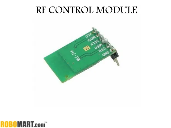
International Journal of Trend in Scientific Research and Development (IJTSRD) @ www.ijtsrd.com eISSN: 2456-6470 The transmitted signals are received by the receiver module placed away from the source of transmission. The system allows one way communication between two nodes, namely, transmission and reception. The RF module has been used in conjunction with a set of four channel encoder/decoder ICs. Here HT12E & HT12D have been used as encoder and decoder respectively. The encoder converts the parallel inputs (from the remote switches) into serial set of signals. These signals are serially transferred through RF to the reception point. The decoder is used after the RF receiver to decode the serial format and retrieve the original signals as outputs. These outputs can be observed on corresponding LEDs. When no signal is received at data pin of HT12D, it remains in standby mode and consumes very less current (less than 1μA) for a voltage of 5V. When signal is received by receiver, it is given to DIN pin (pin14) of HT12D. On reception of signal, oscillator of HT12D gets activated. IC HT12D then decodes the serial data and checks the address bits three times. If these bits match with the local address pins (pins 1- 8) of HT12D, then it puts the data bits on its data pins (pins 10-13) and makes the VT pin high. An LED is connected to VT pin (pin17) of the decoder. This LED works as an indicator to indicate a valid transmission. The corresponding output is thus generated at the data pins of decoder IC. A signal is sent by lowering any or all the pins 10-13 of HT12E and corresponding signal is received at receiver’s end (at HT12D). Address bits are configured by using the by using the first 8 pins of both encoder and decoder ICs. To send a particular signal, address bits must be same at encoder and decoder ICs. By configuring the address bits properly, a single RF transmitter can also be used to control different RF receivers of same frequency. To summarize, on each transmission, 12 bits of data is transmitted consisting of 8 address bits and 4 data bits. The signal is received at receiver’s end which is then fed into decoder IC. If address bits get matched, decoder converts it into parallel data and the corresponding data bits get lowered which could be then used to drive the LEDs. The outputs from this system can either be used in negative logic or NOT gates (like 74LS04) can be incorporated at data pins. Figure3. Data Flow from Transmitter to Receiver Encoder IC (HT12E) receives parallel data in the form of address bits and control bits. The control signals from remote switches along with 8 address bits constitute a set of 12 parallel signals. The encoder HT12E encodes these parallel signals into serial bits. Transmission is enabled by providing ground to pin14 which is active low. The control signals are given at pins 10-13 of HT12E. The serial data is fed to the RF transmitter through pin17 of HT12E. Figure4. Data Transmission Transmitter, upon receiving serial data from encoder IC (HT12E), transmits it wirelessly to the RF receiver. The receiver, upon receiving these signals, sends them to the decoder IC (HT12D) through pin2. The serial data is received at the data pin (DIN, pin14) of HT12D. The decoder then retrieves the original parallel format from the received serial data. Figure6. System Circuit HARDWARE COMPONENTS A.RF Module An RF module (radio frequency module) is a (usually) small electronic device used to transmit and/or receive radio signals between two devices. In an embedded system it is often desirable to communicate with another device wirelessly. This wireless communication may accomplished through optical communication or through radio frequency (RF) communication. For many applications the medium of choice is RF since it does not require line of sight. RF communications incorporate a transmitter and a receiver. They are of various types and ranges. Some can III. be Figure5. Data Receiving @ IJTSRD | Unique Paper ID – IJTSRD26780 | Volume – 3 | Issue – 5 | July - August 2019 Page 1640
International Journal of Trend in Scientific Research and Development (IJTSRD) @ www.ijtsrd.com eISSN: 2456-6470 transmit up to 500 feet. RF modules are widely used in electronic design owing to the difficulty of designing radio circuitry. Good electronic radio design is notoriously complex because of the sensitivity of radio circuits and the accuracy of components and layouts required achieving operation on a specific frequency. In addition, reliable RF communication circuit requires careful monitoring of the manufacturing process to ensure that the RF performance is not adversely affected. RF modules are most often used in medium and low volume products for consumer applications such as garage door openers, wireless alarm or monitoring systems, industrial remote controls, smart sensor applications, and wireless home automation systems. They are sometimes used to replace older infrared communication de-signs as they have the advantage of not requiring line-of-sight operation. Several carrier frequencies are commonly used in commercially available RF modules, including those in the industrial, scientific and medical (ISM) radio bands such as 433.92 MHz, 915 MHz, and 2400 MHz. These frequencies are used because of national and international regulations governing the use of radio for communication. Short Range Devices may also use frequencies available for unlicensed such as 315 MHz and 868 MHz. RF modules may comply with a defined protocol for RF communications such as Zigbee, Bluetooth low energy, or Wi-Fi, or they may implement a proprietary protocol. kept low. As soon as TE returns to high, the encoder output completes its final cycle and then stops. Figure8. HT12E Encoder Figure9. HT12E Pin Diagram Table1. Pin Description of HT12E Function Name A0 A1 A2 A3 A4 A5 A6 A7 Ground AD0 AD1 AD2 AD3 TE Osc2 Osc1 Output Vcc 1 2 3 4 5 6 7 8 9 10 11 12 13 14 15 16 17 18 8 bit Address pins for input Ground (0V) Figure7. RF Modules (transmitter and receiver) B.HT12E Encoder HT12E is an encoder integrated circuit of 2series of encoders. They are paired with 2 series of decoders for use in remote control system applications. It is mainly used in interfacing RF and infrared circuits. The chosen pair of encoder/decoder should have same number of addresses and data format. Simply put, HT12E converts the parallel inputs into serial output. It encodes the 12 bit parallel data into serial for transmission through an RF transmitter. These 12 bits are divided into 8 address bits and 4 data bits.HT12E has a transmission enable pin which is active low. When a trigger signal is received on TE pin, the programmed addresses/data are transmitted together with the header bits via an RF or an infrared transmission medium. HT12E begins a 4-word transmission cycle upon receipt of a transmission enable. This cycle is repeated as long as TE is 4 bit Data/Address pins for input Transmission enable; active low Oscillator input Oscillator output Serial data output Supply voltage; 5V (2.4V-12V) C.HT12D Decoder HT12D is a decoder integrated circuit that belongs to 2series of decoders. This series of decoders are mainly used for remote control system applications, like burglar alarm, car door controller, security system etc. It is mainly provided to interface RF and infrared circuits. They are paired with 2series of encoders. The chosen pair of encoder/decoder should have same number of addresses and data format. @ IJTSRD | Unique Paper ID – IJTSRD26780 | Volume – 3 | Issue – 5 | July - August 2019 Page 1641
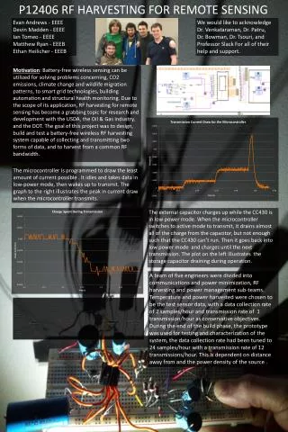
International Journal of Trend in Scientific Research and Development (IJTSRD) @ www.ijtsrd.com eISSN: 2456-6470 In simple terms, HT12D converts the serial input into parallel outputs. It de-codes the serial addresses and data received by, say, an RF receiver, into parallel data and sends them to output data pins. The serial input data is compared with the local addresses three times continuously. Figure10. HT12D Decoder Figure12. Testing Transmission Section Firstly, Transmitter has been tested whether the serial data has been successfully transmitted or not. Testing and result of the transmission section is shown in Figure 11. Secondly, Receiver Section has been checked and tested. Figure11. HT12E Pin Diagram Table2. Pin Description of HT12D Function Pin No 1 2 3 4 5 6 7 8 9 10 11 12 13 14 15 16 17 18 Name A0 A1 A2 A3 A4 A5 A6 A7 Ground D0 D1 D2 D3 Input Osc2 Osc1 VT Vcc Figure13. Testing Receiving Section Finally final circuit has been assembled and testing the response of the system has been conducted. And the fine- tuning of the circuit has been made at that stage. 8 bit Address pins for input Ground (0V) 4 bit Data/Address pins for output Serial data input Oscillator output Oscillator input Valid transmission; active high Supply voltage; 5V (2.4V-12V) IV. The system has been implemented step-by-step and in each step experimental testing has been made to make sure that there is no error. Moreover, the important thing is to get expected results. Tests and results of the main steps involved in implementing the system are described as follows. TESTS AND RESULTS Figure14. Testing the final assembled circuit @ IJTSRD | Unique Paper ID – IJTSRD26780 | Volume – 3 | Issue – 5 | July - August 2019 Page 1642
International Journal of Trend in Scientific Research and Development (IJTSRD) @ www.ijtsrd.com eISSN: 2456-6470 V. In this system, there are mainly two sections; transmitter section and receiver section. Implementation of wireless transmitter and receiver is a new method to overcome from the use of wire. It has also nullified the problem of wire. It is quite efficient, maintenance, and complexity. There is no need to continuously monitor the wire between them while running. And it doesn’t require a line of sight connection between the transmitter and receiver in communication. Moreover, the offer fact is that the transmitter and receiver can be transmitted successfully. The wireless transmitter and receiver can be used in car door, gauge door controllers and home automatic systems. In short, we don’t need lots of cables and wires, and it can be a considerable advantage in terms of time and expense. Acknowledgment The author would like to express her sincere gratitude and deep appreciation to Dr. Theingi, Rector, Technological University (Thanlyin), because of her valuable suggestions CONCLUSION and guidance. The author also thanks to my colleagues in Department of Electronic Engineering, Technological University (Lashio) for their help during developing this system. Reference [1]Harris, Radio Communication in digital Age. Vol 1 [2]http://en.wikipedia.org/wiki/RF_module [3]http://letslearnelectronics.blogspot.com/2012/07/ introduction-to-encoding-and-decoding_1610.html [4]https://www.elprocus.com/rf-module-transmitter- receiver/ [5]http://www.electronicshub.org/wireless-transmitter- and-receiver-using-rf-modules/ [6]http://www.futureelectronics.com/en/wireless-rf- radio-frequency/rf-modules-solutions.aspx @ IJTSRD | Unique Paper ID – IJTSRD26780 | Volume – 3 | Issue – 5 | July - August 2019 Page 1643