Download
1 / 4
40 likes | 59 Vues
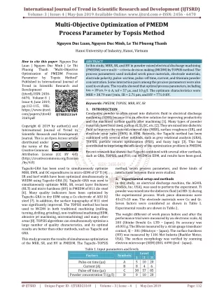
High Tolerance Plasma Arc Cutting System 12mm plate thickness Hardox has been cut by high tolerance plasma arc cutting machine and the unevenness of cutting has been investigated. According to the experimental results, it has been seen that burning of particulars and distribution amount were increased when the cutting was performed measured the speeds. Moreover, it has been noticed that the change the speed which affects the cutting width of plate also change the unevenness of plate with cutting speed. in this study is that quality of the cut can be improved by means of a proper selection of cutting speed . The aim is to see how the cutting system and speed affect material structure up to what depth, it was determined that the hardness from the outer surface to the core decreased, while the hardness near to the outer surface which affected by the high temperature occurred during cutting increased. Patel Jitendra Kumar "Multi-Response Parameter Optimization Hardness and Unevenness Effect of Hardox Cutting Plate by High Tolerance Plasma Arc Cutting System" Published in International Journal of Trend in Scientific Research and Development (ijtsrd), ISSN: 2456-6470, Volume-3 | Issue-2 , February 2019, URL: https://www.ijtsrd.com/papers/ijtsrd21506.pdf Paper URL: https://www.ijtsrd.com/engineering/mechanical-engineering/21506/multi-response-parameter-optimization-hardness-and-unevenness-effect-of-hardox-cutting-plate-by-high-tolerance-plasma-arc-cutting-system/patel-jitendra-kumar<br>

E N D
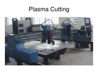
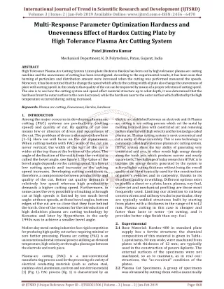
International Journal of Trend in Scientific Research and Development (IJTSRD) Volume: 3 | Issue: 2 | Jan-Feb 2019 Available Online: www.ijtsrd.com e-ISSN: 2456 - 6470 Multi-Response Parameter Optimization Hardness and Unevenness Effect of Hardox Cutting Plate by High Tolerance Plasma Arc Cutting System Patel Jitendra Kumar Mechanical Department, K. D. Polytechnic, Patan, Gujarat, India ABSTRACT High Tolerance Plasma Arc Cutting System 12mm plate thickness Hardox has been cut by high tolerance plasma arc cutting machine and the unevenness of cutting has been investigated. According to the experimental results, it has been seen that burning of particulars and distribution amount were increased when the cutting was performed measured the speeds. Moreover, it has been noticed that the change the speed which affects the cutting width of plate also change the unevenness of plate with cutting speed. in this study is that quality of the cut can be improved by means of a proper selection of cutting speed . The aim is to see how the cutting system and speed affect material structure up to what depth, it was determined that the hardness from the outer surface to the core decreased, while the hardness near to the outer surface which affected by the high temperature occurred during cutting increased. Keywords: Plasma arc cutting, Unevenness, Hardox, hardness 1.INTRODUCTION Among the major concerns in developing plasma arc cutting (PAC) systems are productivity (cutting speed) and quality of cut. By quality of cut one means low or absence of dross and squareness of the cut. The problem of dross is discussed elsewhere [1–5]. Here we will focus on the cut squareness. When cutting metals with PAC; walls of the cut are never vertical: the width of the kerf of the cut is wider at the top than at the bottom of the plate. The angle of declination of the walls from the vertical is called the bevel angle, see figure 1.The value of the bevel angle depends on the cutting speed. It is low at low cutting speeds and increases as the cutting speed increases. Developing cutting conditions is, therefore, a compromise between productivity and quality of the cut. Better cut quality demands a relatively low speed whereas high productivity demands a higher cutting speed. Furthermore, in some cases the very possibility of making a through cut at high speeds is limited by too much bevel angle: at these speeds, at these bevel angles, bottom edges of the cut are so close that they fuse behind the torch. One of the reasons for the introduction of high definition plasma arc cutting technology by Komatsu and later by Hypertherm in the early 1990s was to achieve a smaller bevel angle. Modern day metal cutting industries face rigid competition for producing high quality cut surface requiring minimal or zero further processing. Plasma arc cutting (PAC) is an unconventional metal removal process utilizing an elevated temperature, high velocity arc through a plasma gas between the electrode and work piece. Plasma-arc cutting (PAC) is a non-conventional manufacturing process used for the processing of a variety of electrical conducting materials (such as carbon steel, stainless-steel, aluminium, cast iron and non-ferrous metals) [1] (Fig. 1). PAC process (fig. 1) is characterized by an electric arc stablished between an electrode and th Plasma arc cutting is arc cutting process which cut the metal by melting localized area with constricted arc and removing molten material with high velocity and hot ionized gas called plasma jet. Plasma cutting system is most economical and cut a verity of shape accurately. This is new technology is commonly called high tolerance plasma arc cutting system. HTPAC system share the key ability of generating very constricted and arcs, in other words high energy density along the torch axis which produces narrow and nearly square kerfs. The challenge of today research in HTPAC is to increase the energy density generated by the system to achieve higher cutting thickness without losing the overall quality of cut Steel typically used for the construction of paver’s vehicles and in carpentry, thanks to its excellent quality in welding. Different options exist to profile a sheet or a plate; laser, plasma, oxy-fuel, water-jet and mechanical profiling are those most frequently used. Limiting our attention to railway constructions and railway trucks in particular, they are typically welded structures built by starting from plates with a thickness in the range of 6 to12 mm. Plasma cutting in this case is cheaper and faster than laser or water –jet cutting, and it provides better edge finish than oxy- fuel. 2.Experimental 2.1Base Material: Hardox-400 in standard plate supply has a ferrite structure; the chemical composition of this material is given in Table- 1.specimens, 50 mm wide, were machined from plates with thickness of 12 mm; are typically used in the construction of pavers &plants. The external surfaces of the specimens were not machined, so as to maintain, as in real con- structions, the “as-received” condition of the plates. 2.2Plasma Cut Specimens. A group of specimens was obtained by cutting them with a numerically @ IJTSRD | Unique Reference Paper ID – IJTSRD21506 | Volume – 3 | Issue – 2 | Jan-Feb 2019 Page: 868
International Journal of Trend in Scientific Research and Development (IJTSRD) @ www.ijtsrd.com eISSN: 2456-6470 controlled plasma-cutting machine. The torch was water-cooled and had a nozzle with an outlet diameter of 2.5mm the plasma gas was oxygen, 0.05m3/s, at a pressure of 10.bar.a current setting of 130 amps at 135volts was used. The distance between the torch and the plate was 3.3 mm; 4 =∑ mi 4 i M= ----------- 4 I M = Side unevenness M =Mean unevenness = Side of plate The cutting speed was varies given in table. The plasma cut specimens was also obtained in the longitudinal direction of the plates. The plasma cut surfaces did not look as regular as the milled surfaces The plasma cut edges were not straight and the width of the plate on the reverse side was about 0.8 mm smaller Fig-3 unevenness measurements Chemical composition change the hardness values of hardox- 400 Hardox is no ordinary wear plate its toughness is very high under most extreme condition ,such as high ratio of strain with varying temperature ,this makes hardox particularly resistant to impact. Above table shows that cr percentage is increases in hardox- 400 material in compare of mild steel Modern day metal cutting industries face rigid competition for producing high quality cut surface requiring minimal or zero further processing. Plasma arc cutting (PAC) is an unconventional metal removal process utilizing an elevated temperature, high velocity arc through a plasma gas between the electrode and work piece. The intense heat content and momentum of the plasma vaporizes the work material. Some observations regarding cut quality: Our observations showed the following. Once the arc current, arc voltage (torch to work-piece distance), nozzle orifice and gas flow rate are given, the range of all the cutting speeds canbe divided into two regions: low speed and high speed regions. The boundary that separates these regions is rather arbitrary; however, it helps in developing cutting conditions. When considering metal melting with a plasma jet, it is important to note that the plasma does not directly contact the solid metal. There is a liquid metal layer which separates the hot plasma from the solid metal. The thickness of this layer increases from the top (where it is minimal) to the bottom of the plate, where it is maximal. Since this layer is located ahead of the heat source In this section we consider heat transfer from the plasma to the metal to be cut. The temperature distribution created by a moving heat source has been calculated in a number of works than that on the torch side, 50.05 mm, while the nominal dimension was 50 mm. These differences are generally meaningless in large structures, but can be important in small structures, so that it can be concluded that close. Tolerances cannot be obtained by standard plasma cutting. Besides, small scratches were present on the cut surfaces. The loads to be applied in the tests on plasma cut specimens were evaluated by taking into account their actual dimensions. 2.3 Setting and measurement procedure Table -1: Chemical composition of Hardox Material Hardox-400 material composition C Si Mn P 0.13 0.53 1.24 0.012 0.002 0.65 0.019 0.002 The unevenness is measured by using Plunger dial Depth meter which is Mittu Toyo Company and its Range 0-30mm its accuracy is 0.01mm. The unevenness is average measured all four side. S Cr Mo B Fig-2 unevenness measurements @ IJTSRD | Unique Reference Paper ID – IJTSRD21506 | Volume – 3 | Issue – 2 | Jan-Feb 2019 Page: 869
International Journal of Trend in Scientific Research and Development (IJTSRD) @ www.ijtsrd.com eISSN: 2456-6470 Fig -6 (B) 2100 mm/min Fig-4: Cutting speed Vs Plate thickness of hardox - 400 materials Cutting speeds to be selected according to the thickness of material suggested by machine tool manufacturing company, the tip diameter of the head to be used, blowing rate of cutting gas voltage and ampere amount necessary for the machine tool are listed in Table-2 According to the cutting speed entered the machine tool during cutting the program written in the machine tool memory and feed rate appeared automatically. Above fig. 2 shows that plate thickness increase inversely proportional to cutting speed. The high tolerance plasma arc cutting system used during the experimental study consists of a plasma torch installed on a CNC flexible automatic machining centre for sheet metal processing .with this system ,all the processing can be mounted on to a Y-axis ,work table moves perpendicularly (x-axis)during processing. The axis which controls the plasma torch standoff (z-axis) is servo assisted to provide a constant arc length. All the process parameters can be directly set through the CNC interface. In this experiment 50mmX50mm square plates were cut with 3.3mm ,air pressure taken as 8.5 kg/cm2,133A,on 12 mmplate thickness ,The cutting speed 2200 mm/min is machined tool manufacturing company in this experiment variance of cutting speed 10% above and below InFig-3 shows black line reference values plot, pink line shows experiments values. Fig -6 (C) 2200 mm/min Fig -6{(A), (B), (C), (D)} Hardness variation of graph of hardox-400 material (plate thickness-12mm) Hardness was measured in the hardness of Vickers at intervals of 1 mm and the upper and lower area of the same area from outer surface to the core of specimens cut with various cutting speeds. Hardness values before cutting specimens were determined to compare Hardness measurements of materials whose micro structures had been investigated were performed on a Fig -4 (D) 2300 mm/min Vickers hardness measurement device applying 1 kg weight and the results obtained were recorded in graphics, In the same specimens, hardness was measured at intervals of 1 mm in 4 mm region from outer surface to the core and the hardness variation from outer surface to the core was determined. Different metallurgic specifications and hardness values Then, effects of the method were evaluated according to these variations Plasma cutting method is based on cutting materials at near melting temperature. Since the energy applied and cooling conditions vary, occur. There by, it can be seen that it causes hardness variations relating effects of metallurgic specifications of the material .High heat occurs in the area where plasma gas becomes effective during cutting. Table -2: Unevenness of 12 mm Thickness plate measurements Material thickness (mm) Stand off distance Shielded gas pressure Arc voltage (V) Arc ampere (A) Unevenness Fig-5: Cutting speed Vs unevenness of 12mm plate thickness Above fig-4 shows unevenness decrease with cutting speed decrease but at this speed some dross are produced at this speed Plasma gas Air pressure Fig -6(A) 2000mm/min @ IJTSRD | Unique Reference Paper ID – IJTSRD21506 | Volume – 3 | Issue – 2 | Jan-Feb 2019 Page: 870
International Journal of Trend in Scientific Research and Development (IJTSRD) @ www.ijtsrd.com eISSN: 2456-6470 Material thickness (mm) 12 12 12 12 12 Shielded gas pressure 10 10 10 10 10 Cutting speed (mm/min) 2300 2200 2100 2000 1900 Standoff distance Plasma gas Air Arc voltage Arc Unevenness pressure ampere 3.3 3.3 3.3 3.3 3.3 O2 O2 O2 O2 O2 8.5 8.5 8.5 8.5 8.5 130 130 130 130 130 133 133 134 134 138 525 492 479 468 443 The high tolerance plasma arc cutting system used during the experimental study consists of a plasma torch installed on a CNC flexible automatic machining centre for sheet metal processing. With this system, all the processing can be mounted on to a Y-axis, worktable moves perpendicularly (x-axis) during processing. The axis which controls the plasma torch standoff (z-axis) is servo assisted to provide a constant arc length. All the process parameters can be directly set through the CNC interface. In this experiment 50mmX50mm square plates were cut with 3.3mm, air pressure taken as 8.5 kg/cm2, 133A, on 12 mmplate thickness, The cutting speed 2200 mm/min is machined tool manufacturing company in this experiment variance of cutting speed 10% above and below. Below fig-2 shows unevenness decrease with cutting speed decrease but at this speed some dross are produced at this speed. Also compare with mild steel 15 mm plate thickness which indicate reduce speed with unevenness decrease Conclusion: Cutting speed increase or decrease inversely proportional thickness of plate. The cutting speed reduces results in an excessive amount of molten metal which cannot be completely removed by the momentum of the plasma jet. Further, at low cutting speeds the shape of the cut front changes resulting in a change in the direction of ejection of molten metal. The unevenness of plate increase with increase of cutting speed, so decrease of speed is very important but the at this speed more dross are produced at bottom of plate. It has been found more value of unevenness is in 16mm plate cutting compare of 12mm plate thickness. It was determined that after cutting, in the areas near to outer surface of the part hardness increased, around 390–480 HV, and it decreased towards to the core of the material. References: [1]Abdulkadir Gulluand Umut Ati” Investigation of the effects of plasma arc parameters on the structure variation of AISI 304 and St 52 steels”, Materials & Design, volume27, issue10, 2006, Pages 1157-1162 [2]Kismet kazuomi, “Effect of torch height on cut surface quality of plasma arc cutting”, Volume 2000: pages 213-214 [3]R. BiniB. M. Colosimo, A. E. Kutlu and Monno “Experimental study of the features of the kerf generated by a 200 A high tolerance plasma arc cutting system” journal of material procedure, 2007, pages 1-11. [4]W. JXu, J. C. fang and Y.S Lu, “Study on ceramic cutting by plasma arc, journal of materials processing technology”, volume 129, issues 1-3, pages 152-156 [5]Zeki Cinar, Mohammed. Asmael, Qasim. Zeeshan “Developments in Plasma Arc Cutting (PAC) of Steel Alloys: A Review” Developments in Plasma Arc Cutting (PAC) of Steel Alloys: A Review @ IJTSRD | Unique Reference Paper ID – IJTSRD21506 | Volume – 3 | Issue – 2 | Jan-Feb 2019 Page: 871