Download
1 / 4
40 likes | 66 Vues
Convolutional codes are error correction technique used in noisy channels. Viterbi Algorithm is the most widely used decoding Algorithm, which decodes the sequence in a maximum likelihood sense. But the complexity of the Viterbi decoder increases with the coding rate of the system. Viterbi decoder is the most power hungry module in the Trellis coded modulation system. Viterbi decoding is the best technique for decoding the convolutional codes but it is limited to smaller constraint lengths. The basic building blocks of Viterbi decoder are branch metric unit, add compare and select unit and survivor memory management unit. From the simulation results it is observed that the proposed Viterbi decoder architecture with modified Branch metric calculation can reduce significant amount of computations in order to decrease the hardware usage and to simplify the proceedings. Suman Chandel | Manju Mathur "Viterbi Decoder Plain Sailing Design for TCM Decoders" Published in International Journal of Trend in Scientific Research and Development (ijtsrd), ISSN: 2456-6470, Volume-3 | Issue-5 , August 2019, URL: https://www.ijtsrd.com/papers/ijtsrd26710.pdf Paper URL: https://www.ijtsrd.com/engineering/electronics-and-communication-engineering/26710/viterbi-decoder-plain-sailing-design-for-tcm-decoders/suman-chandel<br>

E N D
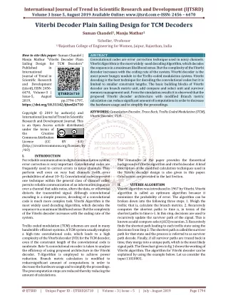
International Journal of Trend in Scientific Research and Development (IJTSRD) Volume 3 Issue 5, August 2019 Available Online: www.ijtsrd.com e-ISSN: 2456 – 6470 Viterbi Decoder Plain Sailing Design for TCM Decoders Suman Chandel1, Manju Mathur2 1Schollar, 2Professor 1,2Rajasthan College of Engineering for Women, Jaipur, Rajasthan, India How to cite this paper: Suman Chandel | Manju Mathur "Viterbi Decoder Plain Sailing Design for TCM Decoders" Published in International Journal of Trend in Scientific Research and Development (ijtsrd), ISSN: 2456- 6470, Volume-3 | Issue-5, August 2019, https://doi.org/10.31142/ijtsrd26710 Copyright © 2019 by author(s) and International Journal of Trend in Scientific Research and Development Journal. This is an Open Access article distributed under the terms of the Creative Commons Attribution License (CC (http://creativecommons.org/licenses/by /4.0) I. INTRODUCTION For reliable communication in digital communication system, error correction is very important. Convolutional codes are frequently used to correct errors in noisy channels. They perform well even on very bad channels (with error probabilities of about 10−3). Convolutional codes represent one technique within the general class of channel codes, permits reliable communication of an information sequence over a channel that adds noise, alters the data, or otherwise distorts the transmitted signal. Although convolutional encoding is a simple process, decoding of a convolutional code is much more complex task. Viterbi Algorithm is the most widely used decoding Algorithm, which decodes the sequence in a maximum likelihood sense. But the complexity of the Viterbi decoder increases with the coding rate of the system. Trellis coded modulation (TCM) schemes are used in many bandwidth- efficient systems. A TCM system usually employs a high-rate convolutional code, which leads to a high complexity of the Viterbi decoder (VD) for the TCM decoder, even if the constraint length of the convolutional code is moderate. Rate ¾ convolutional encoder is taken to analyse the efficiency of using proposed architecture in the Viterbi decoder. T-Algorithm is employed to achieve power reduction. Branch metric calculation is modified to reducesignificant amount of computations in order to decrease the hardware usage and to simplify the proceedings. The precomputation steps are reduced thereby reducing the amount of calculations. ABSTRACT Convolutional codes are error correction technique used in noisy channels. Viterbi Algorithm is the most widely -used decoding Algorithm, which decodes the sequence in a maximum likelihood sense. But the complexity of the Viterbi decoder increases with the coding rate of the system. Viterbi decoder is the most power hungry module in the Trellis coded modulation system. Viterbi decoding is the best technique for decoding the convolutional codes but it is limited to smaller constraint lengths. The basic building blocks of Viterbi decoder are branch metric unit, add compare and select unit and survivor memory management unit. From the simulation results it is observed that the proposed Viterbi decoder architecture with modified Branch metric calculation can reduce significant amount of computations in order to decrease the hardware usage and to simplify the proceedings. KEYWORDS: Convolution Encoder, Trace Back, Trellis Coded Modulation (TCM), Viterbi Decoder, VLSI. The remainder of the paper provides the theoretical background of Viterbi algorithm and viterbi decoder. A brief description of the modified calculation techniques used in the Viterbi decoder design is also given in this paper. Conclusions are provided in the last Section. II. VITERBI ALGORITHM Viterbi algorithm was introduced in 1967 by Viterbi. Viterbi algorithm is called as optimum algorithm because it minimizes the probability of error. The algorithm can be broken down into the following three steps. 1. Weigh the trellis; that is, calculate the branch metrics. 2. Recursively computes the shortest paths to time n, in terms of the shortest paths to time n-1. In this step, decisions are used to recursively update the survivor path of the signal. This is known as add-compare-select (ACS) recursion. 3. Recursively finds the shortest path leading to each trellis state using the decisions from Step 2. The shortest path is called the survivor path for that state and the process is referred to as survivor path decode. Finally, if all survivor paths are traced back in time, they merge into a unique path, which is the most likely signal path. The flowchart given in fig 1 shows the working of Viterbi algorithm. The algorithm for Viterbi decoder can be explained by using the example below. Let us consider the input 11010001. IJTSRD26710 pp.1794-1797, BY 4.0) @ IJTSRD | Unique Paper ID – IJTSRD26710 | Volume – 3 | Issue – 5 | July - August 2019 Page 1794
International Journal of Trend in Scientific Research and Development (IJTSRD) @ www.ijtsrd.com eISSN: 2456-6470 Fig.2. Diagram of Viterbi decoder IV. A.Convolutional encoder Rate ¾ , high rate convolutional encoder is taken to analyse the efficiency of proposed Viterbi decoder architecture. Specifications of this encoder are given in the table 1. Fig 3 shows the structure of rate ¾ convolutional encoder Table 1: Specifications of rate ¾ convolution encoder Parameter Input Length Output length Coding rate Memory register count Constraint length IMPLEMENTATION Symbol K N k/n M K Value 3 4 3/4 6 7 Fig.1. Viterbi Algorithm III. The basic units of Viterbi decoder are branch metric unit, add compare and select unit and survivor memory management unit. The first unit is called branch metric unit. Here the received data symbols are compared to the ideal outputs of the encoder from the transmitter and branch metric is calculated. Hamming distance or the Euclidean distance is used for branch metric computation. The second unit, called path metric computation unit, calculates the path metrics of a stage by adding the branch metrics, associated with a received symbol, to the path metrics from the previous stage of the trellis. The final unit is the trace-back process or register exchange method, where the survivor path and the output data are identified. The trace back (TB) and the register- exchange (RE) methods are the two major techniques used for the path history management in the chip designs of Viterbi decoders. The TB method takes up less area but requires much more time as compared to RE method because it needs to search or trace the survivor path back sequentially. Also, extra hardware is required to reverse the decoded bits. The major disadvantage of the RE approach is that its routing cost is very high especially in the case of long- constraint lengths and it requires much more resources. Fig 2 shows the block diagram of Viterbi decoder which contains a BMU,PMM, ACSU and SMU. decision decoder, a branch metric is a Hamming distance between the received pair of bits and the “ideal” pair. Therefore, a branch metric can take values of 0, 1 and 2. Thus for every input pair we have 4 branch metrics (one for each pair of “ideal” values). For a soft decision decoder, a branch metric is measured using the Euclidean distance. Let x be the first received bit in the pair, y – the second, x0 and y0 – the “ideal” values. Then branch metric is Mb=(x-x0)2 (y-y0)2 VITERBI DECODER Fig.3. Rate ¾ convolution encoder B.Viterbi decoder A Viterbi algorithm consists of the following three major parts: ?Branch metric calculation – calculation of a distance between the input pair of bits and the four possible “ideal” pairs (“00”, “01”, “10”, “11”). ?Path metric calculation – for every encoder state, calculate a metric for the survivor path ending in this state (a survivor path is a path with the minimum metric). ?Traceback – this step is necessary for hardware implementations that don't store full information about the survivor paths, but store only one bit decision every time when one survivor path is selected from the two. C.Branch metric calculation Methods of branch metric calculation are different for hard decision and soft decision decoders. For a hard Further more when we calculate 4 branch matrics for a soft decision decoder, we don’t actually need to know the absolute metric values- only the difference between them makes the sense. So nothing will change if we subtract one value from all four branch metrics. Mb= (x2-2x x0 + x02) + (y2 – 2y y0 + y02) Mb * = Mb – x2 – y2 = (x02 – 2 x x0) + (y02 – 2 y y0) Note that the second formula, Mb * , can be calculated without hardware multiplication: x02 and y02 can be pre- calculated, and multiplication of x by x0 and y by y0 can be done very easily in hardware given that x0 and y0 are constants. It should be also noted that Mb * is a signed variable and should be calculated in 2's complement format. @ IJTSRD | Unique Paper ID – IJTSRD26710 | Volume – 3 | Issue – 5 | July - August 2019 Page 1795
International Journal of Trend in Scientific Research and Development (IJTSRD) @ www.ijtsrd.com eISSN: 2456-6470 D.Path metric calculation Path metrics are calculated using a procedure called ACS (Add-Compare-Select). This procedure is repeated for every encoder state. ?Add –for a given state, we know two states on the previous step which can move to this state, and the output bit pairs that correspond to these transitions. To calculate new path metrics, we add the previous path metrics with the corresponding branch metrics. ?Compare, select– we now have two paths, ending in a given state. One of them (with greater metric) is dropped. As there are 2K-1 encoder states, we have 2K-1 survivor paths at any given time. It is important that the difference between two survivor path metrics cannot exceed δ log(K−1),where δ is a difference between maximum and minimum possible branch metrics. The problem with path metrics is that they tend to grow constantly and will eventually overflow. But, since the absolute values of path metric don't actually matter, and the difference between them is limited, a data type with a certain number of bits will be sufficient. There are two ways of dealing with this problem. Since the absolute values of path metric don't actually matter, we can at any time subtract an identical value from the metric of every path. It is usually done when all path metrics exceed a chosen threshold (in this case the threshold value is subtracted from every path metric). This method is simple, but not very efficient when implemented in hardware. The second approach allows overflow, but uses a sufficient number of bits to be able to detect whether the overflow took place or not. The compare procedure must be modified in this case. E.Trace back method The final step is the trace back procedure, wherein the all the values are consolidated to obtain the final output. If the position of minimum value is 00 or 01, a 0 is obtained in the output. For any other values, a 1 is obtained at the output. In this calculation, the minimum value of the last row is taken and based on its position a 1 or 0 is assigned as one of the output bits. The corresponding path is noted and converted to binary. The minimum value corresponding to that particular path, is noted and once again a position based output bit assignment is made as explained previously, for the row 3. This is repeated for all the remaining rows. Thus,4 output bits are obtained. These bits are then concatenated and a process of bit reversal is made .thus a 4 bit output is derived from an 8 bits input that was given to the Viterbi decoder. In the TB method, the storage can be implemented as RAM and is called the path memory. Comparisons in the ACS unit and not the actual survivors are stored. After at least L branches have been processed, the trellis connections are recalled in the reverse order and the path is traced back through the trellis diagram. The TB method extracts the decoded bits, beginning from the state with the minimum PM. Beginning at this state and tracing backward in time by following the survivor path, which originally contributed to the current PM, a unique path is identified. While tracing back through the trellis, the decoded output sequence, corresponding to the traced branches, is generated in the reverse order. Trace back architecture has a limited memory bandwidth in nature, and thus limits the decoding speed. F.Register Exchange Method The register exchange (RE) method is the simplest conceptually and a commonly used technique. Because of the large power consumption and large area required in VLSI implementations of the RE method, the trace back method (TB) method is the preferred method in the design of large constraint length, high performance Viterbi decoders. In the register exchange, a register assigned to each state contains information bits for the survivor path from the initial state to the current state. In fact, the register keeps the partially decoded output sequence along the path, as illustrated in Figure 6. The register of state S1 at t=3 contains ’101’.This is the decoded output sequence along the hold path from the initial state. The register- exchange method eliminates the need to trace back since the register of the final state contains the decoded output sequence. However, this method results in complex hardware due to the need to copy the contents of all the registers in a stage to the next stage. The survivor path information is applied to the least significant bit of each register, and all the registers perform a shift left operation at each stage to make room for the next bits. Hence, each register fills in the survivor path information from the least significant bit toward the most significant bit. The scheme is called shift update. The shift update method is simple in implementation but causes high switching activity due to the shift operation and, hence, results in high power dissipation. Fig 4 shows the register exchange method. Fig.4. Exchange method V. Viterbi algorithm is the most commonly used algorithm to decode the convolution code. The main drawback is its high computational complexity implementation for large coding rate since its constraint length should be high. In this project, Viterbi decoder with modified Branch metic calculation is designed in order to decrease the hardware usage and to simplify the proceedings. ACKNOWLEDGEMENT I would like to express my special thanks and appreciation to my family and my teachers for their support and encouragement throughout this work. REFERENCES [1]J. Nargis1, D. Vaithiyanathan2, R.Seshasayanan3, “Design of High Speed Low Power Viterbi Decoder for TCM System”, IEEE Transactions on Information Communications and Embedded Systems, Feb 2013 CONCLUSION and power hungry [2]Jinjin He, Huaping Liu, Zhongfeng Wang, Xinming Huang, and Kai Zhang, “High-Speed Low-Power Viterbi Decoder Design for TCM Decoders”, IEEE Transactions on VLSI, VOL. 20, NO. 4,APRIL 2012 [3]Bandwidth-efficient Committee For Space Data System, Matera, Italy, CCSDS 401(3.3.6) Green Book, Issue 1, Apr. 2003. modulations, Consultative @ IJTSRD | Unique Paper ID – IJTSRD26710 | Volume – 3 | Issue – 5 | July - August 2019 Page 1796
International Journal of Trend in Scientific Research and Development (IJTSRD) @ www.ijtsrd.com eISSN: 2456-6470 [4]J. B. Anderson and E. Offer, Reduced-state sequence detection with convolutional codes, IEEE Trans. Inf. Theory, vol. 40, no. 3, pp. 965972, May 1994. Trans. Commun., vol. 45, no. 11, pp. 13891400, Nov. 1997. [8]R. A. Abdallah and N. R. Shanbhag, Error-resilient low- power viterbi decoder architectures, IEEE Trans. Signal Process., vol. 57, no. 12, pp. 49064917, Dec. 2009 [5]Vladimir Stojanovic, Viterbi algorithm implementation, Massachusets Institute of Technology. [6]S. J. Simmons, Breadth-first trellis decoding with adaptive effort, IEEE Trans. Commun., vol. 38, no. 1, pp. 312, Jan. 1990. [9]Anubhuthi Khare, Jagdish Patel, Manish Saxena, FPGA Based Efficient implementation of Viterbi Decoder, International Journal of Engineering and Advanced Technology (IJEAT) ISSN: 2249 – 8958, Volume-1, Issue-1, October 2011 [7]F. Chan and D. Haccoun, Adaptive viterbi decoding of convolutional codes over memoryless channels, IEEE @ IJTSRD | Unique Paper ID – IJTSRD26710 | Volume – 3 | Issue – 5 | July - August 2019 Page 1797