Download
1 / 3
40 likes | 358 Vues
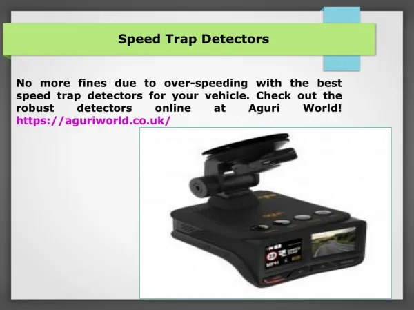
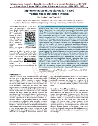
The objective of this paper is to detect the over speed for vehicles on the highway road. Although the maximum speed limit on the highway, many accidents keep on because of over speed driving. It is necessary to solve these problems through electronics circuit. This paper describes speed detection system for vehicles. The highway traffic police are easy to check over speed by using this system. This system mainly consists of Arduino UNO, two IR sensors MD 0138 Infrared Obstacle Avoidance Sensor , 1602A LCD display and buzzer. The detected speed is displayed on LCD. Moreover, if the vehicle crosses the limited speed, this system displays the condition of over speed on LCD and the buzzer is alarmed. Lae Yin Mon | Khin Khin Saw "Design and Construction of Speed Detection System for Vehicles" Published in International Journal of Trend in Scientific Research and Development (ijtsrd), ISSN: 2456-6470, Volume-3 | Issue-3 , April 2019, URL: https://www.ijtsrd.com/papers/ijtsrd23173.pdf Paper URL: https://www.ijtsrd.com/engineering/electronics-and-communication-engineering/23173/design-and-construction-of-speed-detection-system-for-vehicles/lae-yin-mon<br>

E N D
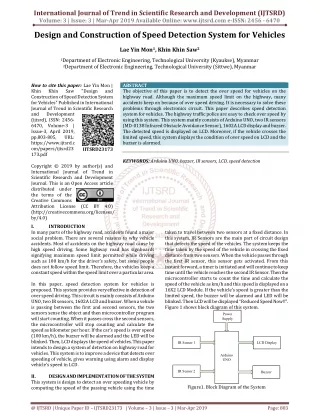
International Journal of Trend in Scientific Research and Development (IJTSRD) Volume: 3 | Issue: 3 | Mar-Apr 2019 Available Online: www.ijtsrd.com e-ISSN: 2456 - 6470 Design and Construction of Speed Detection System forVehicles Lae Yin Mon1, Khin Khin Saw2 1Department of Electronic Engineering, Technological University (Kyaukse), Myanmar 2Department of Electronic Engineering, Technological University (Sittwe), Myanmar How to cite this paper:Lae Yin Mon | Khin Khin Saw "Design and Construction of Speed Detection System for Vehicles" Published in International Journal of Trend in Scientific Research and Development (ijtsrd), ISSN: 2456- 6470, Volume-3 | Issue-3, April 2019, pp.803-805, URL: https://www.ijtsrd.c om/papers/ijtsrd23 173.pdf Copyright © 2019 by author(s) and International Journal of Trend in Scientific Research and Development Journal. This is an Open Access article distributed under the terms of the Creative Commons Attribution License (CC BY 4.0) (http://creativecommons.org/licenses/ by/4.0) I. INTRODUCTION In many parts of the highway road, accidents found a major social problem. There are several reasons to why vehicle accidents. Most of accidents on the highway road cause by high speed driving. Some highway road has signboards signifying maximum speed limit permitted while driving such as 100 km/h for the driver’s safety, but some people does not follow speed limit. Therefore, the vehicles keep a constant speed within the speed limit over a particular area. In this paper, speed detection system for vehicles is proposed. This system provides very effective in detection of over speed driving. This circuit is mainly consists of Arduino UNO, two IR sensors, 1602A LCD and buzzer. When a vehicle is passing between the first and second sensors, the two sensors sense the object and then microcontroller program will start counting. When it passes cross the second sensors, the microcontroller will stop counting and calculate the speed as kilometer per hour. If the car’s speed is over speed (100 km/h), the buzzer will be alarmed and the LED will be blinked. Then, LCD displays the speed of vehicles. This paper intends to design a system of detection on highway road for vehicles. This system is to improve a device that detects over speeding of vehicle, gives warning using alarm and display vehicle’s speed in LCD. II. DESIGN AND IMPLEMENTATION OF THE SYSTEM This system is design to detect an over speeding vehicle by computing the speed of the passing vehicle using the time ABSTRACT The objective of this paper is to detect the over speed for vehicles on the highway road. Although the maximum speed limit on the highway, many accidents keep on because of over speed driving. It is necessary to solve these problems through electronics circuit. This paper describes speed detection system for vehicles. The highway traffic police are easy to check over speed by using this system. This system mainly consists of Arduino UNO, two IR sensors (MD-0138 Infrared Obstacle Avoidance Sensor), 1602A LCD display and buzzer. The detected speed is displayed on LCD. Moreover, if the vehicle crosses the limited speed, this system displays the condition of over speed on LCD and the buzzer is alarmed. KEYWORDS: Arduino UNO, buzzer, IR sensors, LCD, speed detection taken to travel between two sensors at a fixed distance. In this system, IR Sensors are the main part of circuit design that detects the speed of the vehicles. The system keeps the time taken by the speed of the vehicle in crossing the fixed distance from two sensors. When the vehicle passes through the first IR sensor, this sensor gets activated. From this instant forward, a timer is initiated and will continue to keep time until the vehicle reaches the second IR Sensor. Then the microcontroller starts to count the time and calculate the speed of the vehicle as km/h and this speed is displayed on a 16X2 LCD Module. If the vehicle’s speed is greater than the limited speed, the buzzer will be alarmed and LED will be blinked. Then LCD will be displayed “Reduced Speed Now!!”. Figure 1 shows block diagram of this system. IJTSRD23173 Power Supply IR Sensor 1 LCD Display Arduino UNO IR Sensor 2 Buzzer Figure1. Block Diagram of the System @ IJTSRD | Unique Paper ID – IJTSRD23173 | Volume – 3 | Issue – 3 | Mar-Apr 2019 Page: 803
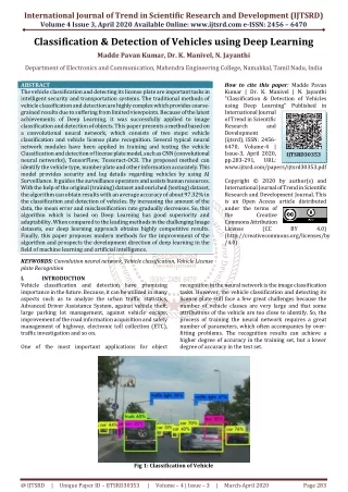
International Journal of Trend in Scientific Research and Development (IJTSRD) @ www.ijtsrd.com eISSN: 2456-6470 III. The overall circuit diagram of speed detection system using IR sensor is shown in figure 2. When a vehicle passes through the first sensor, the infrared ray touches the vehicle that the sensor has detected the object. The output of IR sensor 1 is connected to the pin 8 of the Arduino and LED 1 for sensor 1 is connected to the pin 13 of the Arduino. The second sensor’s infrared ray touches the object and reflects to the sensor and the sensor has sensed the object. The output of IR Sensor 2 is connected to the pin 9 of the Arduino and LED 2 for sensor 2 is connected to the pin 12 of the Arduino. 1602A LCD is used to display the vehicle’s speed. DB 7 to DB 4 of the LCD Pin is connected to the I/O pin 2 to 5 of the Arduino. The RS and E pins of LCD are connected to pins 7 and 6 of Arduino. And then the LCD shows the speed. LCD displays “no vehicle” before the car passes and after the car passes. If the speed is over 100 km/hour, the buzzer will be alarmed and LED 3 will be blink. LCD displays “Reduced Speed Now!!”. The vehicle speed is calculated in microcontroller as km/h. The speed of the vehicle is calculated by this equation. CIRCUIT DESIGN OF SPEED DETECTION SYSTEM IV. The overall flow chart of the system is shown in figure3. Firstly, it initializes the input/output pins of the device. IR sensor 1 is activated and the vehicle is detected come in. If the sensor senses the vehicle, the program starts to count and LED 1 on. If the vehicle is not sensed, LCD displays “No Vehicles” and LEDs off. After that, IR sensor 2 senses the vehicle and continuously the program stops counting and starts to calculate the speed of the vehicle. Microcontroller is counted start time and stop time, and time interval will get from start time and stop time and vehicle speed. And then, the calculated speed is compared with the limited speed. When the calculated speed is greater than limited speed, it alarms on, LED 3 blinks and LCD displays the vehicle’s speed. If not, it will show as “Pass”. If the vehicle is not sensed, LCD displays “No Vehicles” and LEDs off. Finally, the program is ended. OVERALL FLOW CHART OF THE SYSTEM Begin Port Initialization LCD display Speed (km/h) Sense IR 1 The time taken between the two sensors is calculated by this equation. Time=(t2-t1 )ms In this system, the power supply circuit used 12V step down transformer. Regulator LM 7805 is used to get DC 5V. The power supply DC 5V is connected to the VIN pin of the Arduino and the ground pin of the power supply is connected to the GND pin of the Arduino. No Detect object! LED 1 off LED 2 off LED 3 off Yes LED 1 on Sense IR 2 No Detect object! Yes LED1 off LED2 off LED3 off LED 2 on LCD display Speed (km/h) No LCD display (No Vehicle) Over Speed ! (speed>100) Yes Alarm off LED 3 off Alarm on LED 3 blink LCD display Speed (km/h) LCD display Speed (km/h) END Figure3. Overall Flow Chart of the System V. TEST AND RESULT OF SPEED DETECTION SYSTEM In this section, the testing results of speed detection system are shown. Figure 4 shows hardware implementation of overall speed detection system for vehicles. Figure2. Circuit Diagram of Speed Detection System Figure4. Implementation of Over Speed Detection System for Vehicle @ IJTSRD | Unique Paper ID - IJTSRD23173 | Volume – 3 | Issue – 3 | Mar-Apr 2019 Page: 804
International Journal of Trend in Scientific Research and Development (IJTSRD) @ www.ijtsrd.com eISSN: 2456-6470 It consists of Arduino Uno, two IR sensors, LCD display, and buzzer. Arduino Uno is used to acquire the input data from sensors and buzzer is used for alarm system and then show warning message on LCD. In this system limited speed is 100 km/h. The experimental output results can be proved in this section. When the vehicle passes through the sensor 1 and it senses the vehicle. Figure 5 shows the condition of sensor 1 is active. The limited speed is 100 km/h. In this condition, vehicle’s is shown on LED board for over speed condition. Figure 9 shows the vehicle speed 110 km/h and than it will also shows warning message. Figure9. LCD Display for Over Speed (110km/h) If the vehicle speed is greater than the limited speed, LCD shows “Reduced Speed Now!” as shown in figure 10. Figure5. Condition of active sensor 1 When the vehicle passes through the sensor 2 and it senses the vehicle. Figure 6 shows the condition of sensor 2 is active. Figure10. LCD Display for Over Speed Condition VI. Design and construction of speed detection system for vehicles was designed in this paper. This design is based on Arduino microcontroller. The timing condition for the vehicle detection system must be set base on distance between the sensor and speed which can be easily changed and modified using microcontroller. In this paper, the speed limit is specified with 100 km/hr. The calculation of vehicle’s speed and the time taken by it to cross between the sensors is an approximate value. And the speed sensing from sensors is also delay due to the far distance which is installed from one to other. If more accuracy of the speed and time is required, more number of sensors has to be used. The over speed detection system can be further advanced by using GSM module and CCTV camera in the circuit. If any vehicle has crossed the maximum limited speed then this camera will be triggered to take a picture of the vehicle. Employing the over speed detection system offer not only several advantages for traffic but also safety to road users. References [1]https://www.electronicshub.org, arduino-car-speed- detector. DISCUSSION AND CONCLUSION Figure6. Condition of active sensor 1 When the vehicle passes through the sensor 1 and sensor 2, LCD shows the vehicle’s speed. The time taken between two sensors displays on LCD. Figure 7 shows the LCD display for under limited speed condition. In this condition, the vehicle speed is not greater than the limited speed. [2]http://www.ardunio.cc/en/Main/ardunioBoardUno [3]https://www.mathworks.com/22194-vehicle-speed- detection-using-image-procesing Figure7. LCD Display Time Taken (ms) In Figure 8, the vehicle speed is 2km/h on LCD. It is the under speed condition. [4]https://www.winstar.com.tw/products/chacter-lcd- display-module/16x2-lcd-display-html [5]Rana Biswas et al. Int. Journal of Engineering Research and Applications ,ISSN: 2248-9622, Vol. 6, Issue 1, (Part - 4) January 2016, pp.110-112 Figure8. LCD Display for Under Limited Speed @ IJTSRD | Unique Paper ID - IJTSRD23173 | Volume – 3 | Issue – 3 | Mar-Apr 2019 Page: 805