Download
1 / 7
70 likes | 106 Vues
The current study essentially deals with the modeling and analyzing vented and non vented disc brake by CATIA and ANSYS. Finite element models of the brake disc are shaped with CATIA and simulated using ANSYS which is based on the finite element method. This study Structural analysis is done so as to get the strength of the disc brake. Here we discuss disc brake which is used in many vehicles. The stresses and variations developed in vented and non vented disc brakes are discussed using ANSYS software. Disc gets stressed when used in slowing down or stopping the vehicle. So that by using Ansys we can observe variations between stresses of vented and non vented disc brake. Disc brakes are mostly used on front wheels in two wheelers, hatchback cars and also widely used on both front and rear wheels of high end cars. The main aim of this paper is to minimize the Total deformation, Directional deformation, Equivalent stress and strain with best suited Material Analysis is done on both Vented and non vented disc brake. The Geometry of the models is carried out in the CATIA V5 R20 Software and is designed in Mechanical Design. The analysis part is done by using ANSYS R14.5 Software. Meesala Vanajakshi | Pothuraju. V. V. Satyanarayana | E. Lakshmi Devi "Static Structural Analysis of Vented and Non Vented Disc Brake" Published in International Journal of Trend in Scientific Research and Development (ijtsrd), ISSN: 2456-6470, Volume-3 | Issue-5 , August 2019, URL: https://www.ijtsrd.com/papers/ijtsrd26450.pdf Paper URL: https://www.ijtsrd.com/engineering/mechanical-engineering/26450/static-structural-analysis-of-vented-and-non-vented-disc-brake/meesala-vanajakshi<br>

E N D
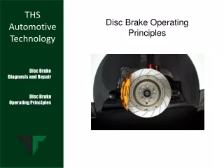
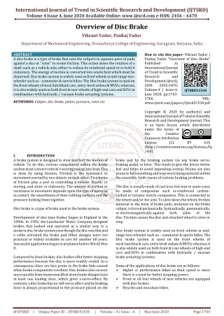
International Journal of Trend in Scientific Research and Development (IJTSRD) Volume 3 Issue 5, August 2019 Available Online: www.ijtsrd.com e-ISSN: 2456 – 6470 Static Structural Analysis of Vented and Non Vented Disc Brake Meesala Vanajakshi1, Pothuraju. V. V. Satyanarayana2, E. Lakshmi Devi3 1Post Graduate Student, 2,3Assistant Professor 1,3Department of Mechanical Engineering, Visakha Technical Campus, Narava, Visakhapatnam, India 2Department of Mechanical Engineering, Avanthi Institute of Engineering and Technology, 2Makavarapalem, Visakhapatnam, India How to cite this paper: Meesala Vanajakshi | Pothuraju. Satyanarayana | E. Lakshmi Devi "Static Structural Analysis of Vented and Non Vented Disc Brake" International Journal of Trend in Scientific Research and Development (ijtsrd), ISSN: 2456- 6470, Volume-3 | Issue-5, August 2019, pp.721-727, https://doi.org/10.31142/ijtsrd26450 Copyright © 2019 by author(s) and International Journal of Trend in Scientific Research and Development Journal. This is an Open Access article distributed under the terms of the Creative Commons Attribution License (CC (http://creativecommons.org/licenses/by /4.0) For example, in friction braking it is converted into heat, and in regenerative braking it is converted into electricity or compressed air etc. During a braking operation not all the kinetic energy is converted into the desired form, e.g. in friction braking some energy might be dissipated in the form of vibrations. So to get optimum performance in demanding applications, ventilation is introduced in the brake discs which increases the cooling rate. Brake discs could be divided into two categories: 1.Ventilated disk brake 2.Non-Ventilated or Solid disk brake 2.PRINCIPLE OF BRAKING SYSTEM A brake is a device by means of which artificial frictional resistance is applied to moving machine member, in order to stop the motion of a machine. Break play a major role in moving automotive vehicles. A disk brake consists of a cast iron disc bolted to the wheel hub and a stationary hosing called caliper the caliper is connected to some stationary part of the vehicle like the axle casing or stub axle as in two parts each part containing a piston. in between each piston and the disc, there is a friction pad held in position by retaining pins, spring plates etc. passages are drilled in the caliper for the fluid enter or leave ABSTRACT The current study essentially deals with the modeling and analyzing vented and non vented disc brake by CATIA and ANSYS. Finite element models of the brake-disc are shaped with CATIA and simulated using ANSYS which is based on the finite element method. This study Structural analysis is done so as to get the strength of the disc brake. Here we discuss disc brake which is used in many vehicles. The stresses and variations developed in vented and non- vented disc brakes are discussed using ANSYS software. Disc gets stressed when used in slowing down or stopping the vehicle. So that by using Ansys we can observe variations between stresses of vented and non-vented disc brake. Disc brakes are mostly used on front wheels in two-wheelers, hatchback cars and also widely used on both front and rear wheels of high end cars. The main aim of this paper is to minimize the Total deformation, Directional deformation, Equivalent stress and strain with best suited Material Analysis is done on both Vented and non vented disc brake. The Geometry of the models is carried out in the CATIA V5 R20 Software and is designed in Mechanical Design. The analysis part is done by using ANSYS R14.5 Software. KEYWORDS: vented, Non vented, hatchback, Catia and Ansys 1.INTRODUCTION A vehicle requires a brake system to stop or adjust its speed with changing road and traffic conditions. The basic principle used in braking systems is to convert the kinetic energy of a vehicle into some other form of energy. V. V. Published in IJTSRD26450 BY 4.0) each housing the passages are also connected to another one for bleeding. Each cylinder and piston. When the brakes are applied, hydraulically actuated pistons move the friction pads into contact with the rotating disc, applying equal and opposite forces on the disc. Due to the friction between disc and pad surfaces the kinetic energy of the rotating wheel is converted into heat, by which vehicle is to stop after a certain distance. On releasing the brakes the brakes rubber-sealing ring acts as return spring and retract the pistons and the friction pads away from the disc. 3.DESIGN OF DISC BRAKE Designing of vented and non vented disc brake rotor using the ISO standard dimensions of BMW car in CATIA V5. Fig 1: Three Dimensional Vented Disc brake @ IJTSRD | Unique Paper ID – IJTSRD26450 | Volume – 3 | Issue – 5 | July - August 2019 Page 721
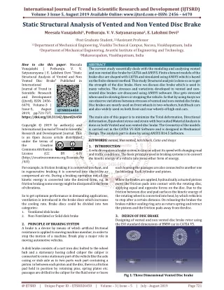
International Journal of Trend in Scientific Research and Development (IJTSRD) @ www.ijtsrd.com eISSN: 2456-6470 R is the construction type i.e., Radial 18 is the rim diameter in inches Aspect ratio = section height / section width Section height = Section width * Aspect ratio = 315 * 0.60 = 189 mm = 0.189 m Rim radius = 144 mm = 0.144 m Tyre radius = Rim Radius + Section height = 0.144 + 0.189= 0.333 m According to the industrial standards: μ = 0.7 R=0.333m d = 37 mm = 0.037m F=1400lbs = 1400 * 0.453 = 634.2 kg = 634.2 * 9.81 = 6221.5 N S = 1.5 Bending moment M = ((μ*R) + d)* F * S = ((0.7 * 0.333) + 0.037) * 6221.5 * 1.5 = 2520.65 Nm = 252065Nmm Fig 2: Three Dimensional Non Vented Disc brake 4.DESIGN CALCULATION BENDING TEST The bending moment to be imparted in the test shall be in accordance with the following formula: M = ((μ*R) + d)* F * S M = Bending moment in ‘Nm’ μ = Friction Coefficient between the tire and the road surface(no units) R = Radius of the tyre applicable to the wheel in ‘m’ d = Offset of the wheel in ‘m’ F = Maximum load acting on the tire in ‘N’ S = Coefficient specified according to the standards. Tyre specification Radial 315/60-R18 315 is the section width in millimeters 60 is the Aspect ratio in percentage 5.MATERIAL SELECTION It plays an important role in product design and manufacturing. This is guided by the way the material behaves in the real-time conditions according to its use. The material response to the environmental stimulus is called property. Based on the application and usage of material, its properties become significant. Properties Gray Cast Iron Density 7.2e-006 kg mm^-3 Young's Modulus 1.1e+005 MPa Poisson's Ratio 0.28 Coefficient of Thermal Expansion 1.1e-005 C^-1 Specific Heat 4.47e+005 mJ kg^-1 C^-1 5.22e+005 mJ kg^-1 C^-1 Thermal Conductivity 5.2e-002 W mm^-1 C^-1 Resistivity 9.6e-005 ohm mm STATIC STRUCTURAL ANALYSIS Workbench allows you to copy systems in order to efficiently perform and compare multiple similar analyses. Static analysis is performed over a structure when the loads and boundary conditions remain stationary and do not change over Time. it is assumed that the load or field conditions are applied gradually. 6.RESULTS TESTING AND VALIDATION OF VENTED & NON VENTED DISC BRAKE CROSS SECTION TOTAL DEFORMATION (mm) VENTED 0.0045958 NON VENTED 0.051897 VENTED 0.0054448 NON VENTED 0.055934 VENTED 0.002654 NON VENTED 0.028952 Tab 1: Comparison results for static structural Ansys Titanium Alloy 4.62e-006 kg mm^-3 96000 MPa 0.36 9.4e-006 C^-1 Stainless Steel 7.75e-006 kg mm^-3 1.93e+005 MPa 0.31 1.7e-005 C^-1 4.8e+005 mJ kg^-1 C^-1 2.19e-002 W mm^-1 C^-1 1.51e-002 W mm^-1 C^-1 1.7e-003 ohm mm 7.7e-004 ohm mm EQUIVALENT STRESS (Mpa) 8.9412 17.901 8.7275 17.32 8.8766 17.707 MATERIAL MODEL EQUIVALENT STRAIN 8.2068e-5 0.0001646 9.1893e-5 0.00018267 4.6457e-5 9.2832e-5 GRAY CAST IRON TITANIUM ALLOY STAINLESS STEEL @ IJTSRD | Unique Paper ID – IJTSRD26450 | Volume – 3 | Issue – 5 | July - August 2019 Page 722
International Journal of Trend in Scientific Research and Development (IJTSRD) @ www.ijtsrd.com eISSN: 2456-6470 Graph 1: Deformation of different disc brake models 6.1.STATIC ANALYSIS OF DISK BRAKE FOR VENTED MODELS RESULTS AND ANALYSIS OF VENTED DISC BRAKE 1.GRAY CAST IRON Mass= 8.4311kg, Nodes= 34213, Elements=18347. Fig 3: Geometry Diagram Fig 5: Total deformation Fig 4: Mesh diagram Fig 6: Equivalent stress @ IJTSRD | Unique Paper ID – IJTSRD26450 | Volume – 3 | Issue – 5 | July - August 2019 Page 723
International Journal of Trend in Scientific Research and Development (IJTSRD) @ www.ijtsrd.com eISSN: 2456-6470 Fig 7: Equivalent Elastic strain 2.TITANIUM ALLOY Mass= 5.4099 kg, Nodes= 34213, Elements= 18347. Fig 10: Equivalent Elastic strain 3.STAINLESS STEEL Mass= 9.0751 kg, Nodes= 34213, Elements= 18347. Fig 8: Total deformation Fig 11: Total deformation Fig 9: Equivalent stress Fig 12: Equivalent stress @ IJTSRD | Unique Paper ID – IJTSRD26450 | Volume – 3 | Issue – 5 | July - August 2019 Page 724
International Journal of Trend in Scientific Research and Development (IJTSRD) @ www.ijtsrd.com eISSN: 2456-6470 1.GRAY CAST IRON Mass= 3.657kg, Nodes= 16537, Elements= 7967. Fig 13: Equivalent Elastic strain 6.2.STATIC ANALYSIS OF DISC BRAKE FOR NON VENTED MODELS RESULTS AND ANALYSIS OF NON VENTED DISC BRAKE Fig 16: Total deformation Fig 17: Equivalent stress Fig 14: Geometry Diagram Fig 18: Equivalent Elastic strain Fig 15: Mesh diagram @ IJTSRD | Unique Paper ID – IJTSRD26450 | Volume – 3 | Issue – 5 | July - August 2019 Page 725
International Journal of Trend in Scientific Research and Development (IJTSRD) @ www.ijtsrd.com eISSN: 2456-6470 2.TITANIUM ALLOY Mass= 2.3466kg, Nodes= 16537, Elements= 7967. 3.STAINLESS STEEL Mass= 3.9363kg, Nodes= 16537, Elements= 7967. Fig 19: Total deformation Fig 22: Total deformation Fig 20: Equivalent stress Fig 23: Equivalent stress Fig 21: Equivalent Elastic strain Fig 24: Equivalent Elastic strain @ IJTSRD | Unique Paper ID – IJTSRD26450 | Volume – 3 | Issue – 5 | July - August 2019 Page 726
International Journal of Trend in Scientific Research and Development (IJTSRD) @ www.ijtsrd.com eISSN: 2456-6470 [5]Haripal Singh and Harsh Deep Shergill, (2012) Thermal Analysis of Disc Brake Using Comsol International Journal on Emerging Technologies. 7.CONCLUSION It is observed that the Vented type disc brakes can provide better Static Structural analysis than the Non Vented disc Brake. It provides useful design tools and improvement of the brake performance in the disk brake system. We can say that from all the values obtained from the analysis i.e. the Total Deformation, Equivalent Stress and Equivalent strain. exhibit that the vented disc is best-suited design. Comparing the different results obtained from the analysis, it is concluded that disk brake with vents and of material Stainless steel is observed best possible combination for the present application. The finite element results show that the performance of disc brake used in this study of geometry and material properties. 8.REFERENCES [1]R. S. KHURMI and J .K.GUPTA, (2008). Machine Design, Division of S. Chand and Company Ltd, Ram Nagar New Delhi. [6]Daniel Das. A Christo Reegan Raj. V, Preethy. S and RamyaBharani. G. (2013). Structural and Thermal Analysis of [7]Disc Brake in Automobiles.”International Journal of Latest Trends in Engineering and Technology. [8]V. Chengal Reddy, M. Gunasekhar Reddy and Dr. G. HarinathGowd (2013), Modeling and Analysis of FSAE Car Disc Brake Using FEM. International Journal of Emerging Technology and Advanced Engineering. [9]Guru Murthy Nathi1, T N Charyulu, K. Gowtham and P Satish Reddy,(2012), THERMAL ANALYSIS OF DISC BRAKE, GURU MURTHY NATHI, et al ISSN: 2319 – 1163 Volume:1 Issue:4 COUPLED STRUCTURAL [10]K. NareshBabu STRUCTURAL DESIGN AND THERMAL ANALYSIS OF CARDIAC BRAKE ROTOR. Babu, et al, International Journal of Advanced Engineering Research and Studies. and T.Siva Krishna, (2013) [2]Joe Y. G. Cha, Analysis of disc brake instability due to friction-induced vibration, International of automotive technology, vol9, No 2, PP 169-171. [11]V. M. M. Thilak, R. Krishnaraj, Dr. M. Sakthivel, K. Kanthavel, Deepan Marudachalam and M. G, R.Palani, (2011),” Transient Thermal and Structural Analysis of the Rotor-Disc of Disc Brake”, International Journal of Scientific & Engineering Research Volume 2, Issue 8. [3]M. Bayat, The effect of ceramic in a combination of the functionally graded rotating disc, International journal of computational method, vol9, No 2,2012,22 pages. [4]Utz von Wagner, (2011) Influence of dynamic brake pad properties on automotive disc brake squeal, PAMM, vol11, Issue 1, Paper 345-346. @ IJTSRD | Unique Paper ID – IJTSRD26450 | Volume – 3 | Issue – 5 | July - August 2019 Page 727