Linear Static Structural Analysis Overview
Learn linear static structural analyses in ANSYS Simulation, covering geometry, contact types, loads, results, and more. Understand the basics and assumptions for linear static analysis. Discover material properties and solid body contact in assemblies.

Linear Static Structural Analysis Overview
E N D
Presentation Transcript
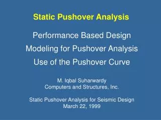
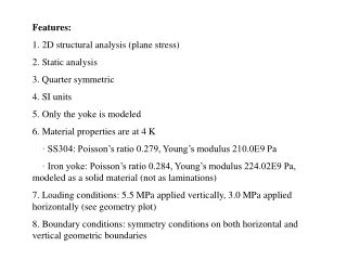
Chapter Four Static Structural Analysis
Chapter Overview • In this chapter, performing linear static structural analyses in Simulation will be covered: • Geometry and Elements • Contact and Types of Supported Assemblies • Environment, including Loads and Supports • Solving Models • Results and Postprocessing • The capabilities described in this section are generally applicable to ANSYS DesignSpace Entra licenses and above. • Some options discussed in this chapter may require more advanced licenses, but these are noted accordingly. • Free vibration, harmonic, and nonlinear structural analyses are not discussed here but in their respective chapters. March 29, 2005 Inventory #002215 4-2
Basics of Linear Static Analysis • For a linear static structural analysis, the displacements {x} are solved for in the matrix equation below:This results in certain assumptions related to the analysis: • [K] is essentially constant • Linear elastic material behavior is assumed • Small deflection theory is used • Some nonlinear boundary conditions may be included • {F} is statically applied • No time-varying forces are considered • No inertial effects (mass, damping) are included • It is important to remember these assumptions related to linear static analysis. Nonlinear static and dynamic analyses are covered in later chapters. March 29, 2005 Inventory #002215 4-3
A. Geometry • In structural analyses, all types of bodies supported by Simulation may be used. • For surface bodies, thickness must be supplied in the “Details” view of the “Geometry” branch. • The cross-section and orientation of line bodies are defined within DesignModeler and are imported into Simulation automatically. • For line bodies, only displacement results are available. March 29, 2005 Inventory #002215 4-4
… Point Mass • A Point Mass is available under the Geometry branch to mimic weight not explicitly modeled • A point mass is associated with surface(s) only • The location can be defined by either: • (x, y, z) coordinates in any user-defined Coordinate System • Selecting vertices/edges/surfaces to define location • The weight/mass is supplied under “Magnitude” • In a structural static analysis, the point mass is affected by “Acceleration,” “Standard Earth Gravity,” and “Rotational Velocity”. No other loads affect a point mass. • The mass is ‘connected’ to selected surfacesassuming no stiffness between them. This isnota rigid-region assumption but similar to a distributed mass assumption. • No rotational inertial terms are present. March 29, 2005 Inventory #002215 4-5
… Point Mass • A point mass will be displayed as a round, grey sphere • As noted previously, only inertial loads affect the point mass. • This means that the only reason to use a point mass in a linear static analysis is to account for additional weight of a structure not modeled. Inertial loads must be present. • No results are obtained for the Point Mass itself. March 29, 2005 Inventory #002215 4-6
… Material Properties • The required structural material properties are Young’s Modulus and Poisson’s Ratio for linear static structural analyses • Material input is under the “Engineering Data” branch, and material assignment is per part under the “Geometry” branch • Mass density is required if any inertial loads are present • Thermal expansion coefficient and thermal conductivity are required if any thermal loads are present • Thermal loading not available with an ANSYS Structural license • Negative thermal expansion coefficient may be input (shrinkage) • Stress Limits are needed if a Stress Tool result is present • Fatigue Properties are needed if Fatigue Tool result is present • Requires Fatigue Module add-on license • Specific loading and result tools will be discussed later March 29, 2005 Inventory #002215 4-7
… Material Properties • Engineering Data view of sample material shown below: March 29, 2005 Inventory #002215 4-8
B. Assemblies – Solid Body Contact • When importing assemblies of solid parts, contact regions are automatically created between the solid bodies. • Surface-to-surface contact allows non-matching meshes at boundaries between solid parts • Tolerance controls under “Contact” branch allows the user to specify distance of auto contact detection via slider bar March 29, 2005 Inventory #002215 4-9
… Assemblies – Solid Body Contact • In Simulation, the concept of contact and target surfaces are used for each contact region. • One side of the contact region is comprised of “contact” face(s), the other side of the region is made of “target” face(s). • The integration points of the contact surfaces are restricted from penetrating through the target surfaces (within a given tolerance). The opposite is not true, however. • When one side is the contact and the other side is the target, this is called asymmetric contact. On the other hand, if both sides are made to be contact & target, this is called symmetric contact since neither side can penetrate the other. • By default, Simulation uses symmetric contact for solid assemblies. • For ANSYS Professional licenses and above, the user may change to asymmetric contact, as desired. March 29, 2005 Inventory #002215 4-10
… Assemblies – Solid Body Contact • Four contact types are available: • Bonded and No Separation contact are basically linear behavior and require only 1 iteration • Frictionless and Rough contact are nonlinear and require multiple iterations. However, note that small deflection theory is still assumed. • When using these options, an interface treatmentoption is available, set either as “Actual Geometry(and Specified Offset)” or “Adjusted to Touch.”The latter allows the user to have ANSYS close the gap to ‘just touching’ position. This is availablefor ANSYS Professional and above. March 29, 2005 Inventory #002215 4-11
… Assemblies – Solid Body Contact • For the advanced user, some of the contact options can be modified • Formulation can be changed from “Pure Penalty” to “Augmented Lagrange,” “MPC,” or “Normal Lagrange.” • “MPC” is applicable to bonded contact only • “Augmented Lagrange” is used in regular ANSYS • The pure Penalty method can be thought of as adding very high stiffness between interface of parts, resulting in negligible relative movement between parts at the contact interface. • MPC formulation writes constraint equations relating movement of parts at interface, so no relative movement occurs. This can be an attractive alternative to penalty method for bonded contact. March 29, 2005 Inventory #002215 4-12
In this case, the gap between the two parts is bigger than the pinball region, so no automatic gap closure will be performed. … Assemblies – Solid Body Contact • Advanced options (continued): • As explained in Chapter 3, the pinball region can be input and visualized • The pinball region defines location of near-field open contact. Outside of the pinball region is far-field open contact. • Originally, the pinball region was meant to more efficiently process contact searching, but this is also used for other purposes, such as bonded contact • For bonded or no separation contact, if gap or penetration is smaller than pinball region, the gap/penetration is automatically excluded • Other advanced contact options will be discussed in Chapter 11. March 29, 2005 Inventory #002215 4-13
… Assemblies – Surface Body Contact • For ANSYS Professional licenses and above, mixed assemblies of shells and solids are supported • Allows for more complex modeling of assemblies, taking advantage of the benefits of shells, when applicable • More contact options are exposed to the user • Contact postprocessing is also available (discussed later) March 29, 2005 Inventory #002215 4-14
… Assemblies – Surface Body Contact • Edge contact is a subset of general contact • For contact including shell faces or solid edges, only bonded or no separation behavior is allowed. • For contact involving shell edges, only bonded behavior using MPC formulation is allowed. • For MPC-based bonded contact, user can set the search direction (the way in which the multi-point constraints are written) as eitherthe target normal or pinball region. • If a gap exists (as is often the case with shell assemblies), the pinball region can beused for the search direction to detect contact beyond a gap. March 29, 2005 Inventory #002215 4-15
… Assemblies – Contact Summary • A summary of contact types and options available in Simulation is presented in the table below: • This table is also in the Simulation online help. Please refer to this table to determine what options are available. • Note that surface body faces can only participate in bonded or no separation contact. Surface body edges allow MPC-based bonded contact only. March 29, 2005 Inventory #002215 4-16
… Assemblies – Spot Weld • Spot welds provide a means of connecting shell assemblies at discrete points • For ANSYS DesignSpace licenses, shell contact is not supported, so spotwelds are the only way to define a shell assembly. • Spotweld definition is done in the CAD software. Currently, only DesignModeler and Unigraphics define spotwelds in a manner that Simulation supports. • Spotwelds can also be created in Simulation manually, but only at discrete vertices. March 29, 2005 Inventory #002215 4-17
C. Loads and Supports • There are four types of structural loads available: • Inertial loads • These loads act on the entire system • Density is required for mass calculations • These are only loads which act on defined Point Masses • Structural Loads • These are forces or moments acting on parts of the system • Structural Supports • These are constraints that prevent movement on certain regions • Thermal Loads • Structurally speaking, the thermal loads result in a temperature field, which causes thermal expansion on the model. March 29, 2005 Inventory #002215 4-18
. . . Time Type • A time type option is available at certain license levels. • The default time type for loading is “static” • “Sequence” and “harmonic” time types are available as options (harmonic analysis is covered in the Advanced WB training) • Sequence loading allows a series of static time steps to be set up in advance and solved at once • Sequenced results can be reviewed step by step March 29, 2005 Inventory #002215 4-19
. . . Time Type • Specify the desired number of sequence steps in the details of the Environment. • Enter the value of the load for each step by first highlighting the desired step in the graphics window. • The chart in the graphics window displays the variation of the load. March 29, 2005 Inventory #002215 4-20
. . . Time Type • The worksheet view provides a graphical representation of each load’s sequence. • Results of a sequenced simulation can be reviewed by highlighting the quantity of interest and picking the desired sequence from the graphics window. March 29, 2005 Inventory #002215 4-21
Loads/Supports not listed in the table do not have direction associated with it, so Coordinate Systems are not applicable. … Directional Loads • For most loads/supports which have an orientation, the direction can be defined by components in any Coordinate System • The Coordinate System (CS) has to be defined prior to specifying the loading. Only Cartesian coordinate systems may be used for loading/support orientation. • In the Details view, change “Define By” to “Components”. Then, select the appropriate Cartesian CS from the pull-down menu. • Specify x, y, and/or z components, which are relative to the selected Coordinate System • Not all loads/supports support use of CS: March 29, 2005 Inventory #002215 4-22
… Acceleration & Gravity • An acceleration can be defined on the system • Acceleration acts on entire model in length/time2 units. • Users sometimes have confusion over notation of direction. If acceleration is applied to system suddenly, the inertia resists the change in acceleration, so the inertial forces are in the opposite direction to applied acceleration • Acceleration can be defined by Components or Vector • Standard Earth Gravity can also be applied as a load • Value applied is 9.80665 m/s2 (in SI units) • Standard Earth Gravity direction can only be defined along one of three World Coordinate System axes. • Since “Standard Earth Gravity” is defined as an acceleration, define the direction as opposite to gravitational force, as noted above. March 29, 2005 Inventory #002215 4-23
… Rotational Velocity • Rotational velocity is another inertial load available • Entire model spins about an axis at a given rate • Can be defined as a vector, using geometry for axis and magnitude of rotational velocity • Can be defined by components, supplying origin and components in World Coordinate System • Note that location of axis is very important since model spins around that axis. • Default is to input rotational velocity in radians per second. Can be changed in “Tools > Control Panel > Miscellaneous > Angular Velocity” to revolutions per minute (RPM) instead. March 29, 2005 Inventory #002215 4-24
… Forces and Pressures • Pressure loading: • Pressures can only be applied to surfaces and always act normal to the surface • Positive value acts into surface (i.e., compressive)negative value acts outward from surface (i.e., suction) • Units of pressure are in force per area • Force loading: • Forces can be applied on vertices, edges, or surfaces. • The force will be distributed on all entities. This means that if a force is applied to two identical surfaces, each surface will have half of the force applied. Units are mass*length/time2 • A force is defined via vector and magnitude or by components (in user-defined Coordinate System) March 29, 2005 Inventory #002215 4-25
… Bearing Load • Bearing Load (was called “Bolt Load” in prior releases): • Bearing Loads are for cylindrical surfaces only. Radial component will be distributed on compressive side using projected area. Example of radial distribution shown below.Axial component is distributed evenly on cylinder. • Use only one bearing load per cylindrical surface. If the cylindrical surface is split in two, however, be sure to select both halves of cylindrical surface when applying this load. • Load is in units of force • Bearing load can be defined via vector and magnitude or by components (in anyuser Coordinate System). March 29, 2005 Inventory #002215 4-26
… Moment Load • Moment Load: • For solid bodies, a moment can be applied on any surface • If multiple surfaces are selected, the moment load gets apportioned about those selected surfaces • A vector and magnitude or components (in user-defined Coordinate System) can define the moment. The moment acts about the vector using the right-hand rule • For surface bodies, a moment can also be applied to a vertex or edge with similar definition via vector or components as with a surface-based moment • Units of moment are in Force*length. March 29, 2005 Inventory #002215 4-27
… Remote Load • Remote Load: • Allows the user to apply an offset force on a surface or edge of a surface body • The user supplies the origin of the force (using vertices, a cylinder, or typing in (x, y, z) coordinates). A user-defined Coordinate System may be used to reference the location. • The force can then be defined by vector and magnitude or by components (components for direction is in Global CS) • This results in an equivalent force on the surface plus a moment caused by the moment arm of the offset force • The force is distributed on the surfacebut includes the effect of the momentarm due to the offset of the force • Units are in force (mass*length/time2) March 29, 2005 Inventory #002215 4-28
… Supports (General) • Fixed Support: • Constraints all degrees of freedom on vertex, edge, or surface • For solid bodies, prevents translations in x, y, and z • For surface and line bodies, prevents translations and rotations in x, y, and z • Given Displacement: • Applies known displacement on vertex, edge, or surface • Allows for imposed translational displacement in x, y, and z (in user-defined Coordinate System) • Entering “0” means that the direction is constrained. • Leaving the direction blank means that the entity is free to move in that direction March 29, 2005 Inventory #002215 4-29
… Supports (Solid Bodies) • Frictionless Support: • Applies constraint in normal direction on surfaces • For solid bodies, this support can be used to apply a ‘symmetry’ plane boundary condition since ‘symmetry’ plane is same as normal constraint • Cylindrical Constraint: • Applied on cylindrical surfaces • User can specify whether axial, radial, or tangential components are constrained • Suitable for small-deflection (linear) analysis only March 29, 2005 Inventory #002215 4-30
… Supports (Solid Bodies) • Compression Only Support: • Applies a compression-only constraint normal to any given surface. This prevents the surface to move in the positive normal direction only. • A way to think of this support is to imagine a ‘rigid’ structure which has the same shape of the selected surface. Note that the contacting (compressive) areas are not known beforehand. • Can be used on a cylindrical surface to model a (referred to as “Pinned Cylinder” 7.1) • Notice the example on the right,where the outline of the undeformed cylinder is shown. The compressive side retains the shapeof the original cylinder, but the tensile side is free to deform. • This requires an iterative (nonlinear) solution. March 29, 2005 Inventory #002215 4-31
… Supports (Line/Surface Bodies) • Simply Supported: • Can be applied on edge or vertex of surface or line bodies • Prevents all translations but all rotations are free • Fixed Rotation: • Can be applied on surface, edge, or vertex of surface or line bodies • Constrains rotations but translations are free March 29, 2005 Inventory #002215 4-32
… Summary of Supports • Supports and ContactRegions may both be thought of as being boundary conditions. • Contact Regions provides a ‘flexible’ boundary condition between two existing parts explicitly modeled • Supports provide a ‘rigid’ boundary condition between the modeled part an a rigid, immovable part not explicitly modeled • If Part A, which is of interest, is connected to Part B, consider whether both parts need to be analyzed (with contact) or whether supports will suffice in providing the effect Part B has on Part A. • In other words, is Part B ‘rigid’ compared to Part A? If so, a support can be used and only Part A modeled. If not, one may need to model both Parts A and B with contact. March 29, 2005 Inventory #002215 4-33
… Thermal Loading • Temperature causes thermal expansion in the model • Thermal strains are calculated as follows:where a is the thermal expansion coefficient (CTE), Tref is the reference temperature at which thermal strains are zero, T is the applied temperature, and eth is the thermal strain. • Thermal strains do not cause stress by themselves. It is the constraint, temperature gradient, or CTE mismatch that produce stress. • CTE is defined in “Engineering Data” and has units of strain per temperature • The reference temperature is defined in the“Environment” branch March 29, 2005 Inventory #002215 4-34
… Thermal Loading • Thermal loads can be applied on the model • Any temperature loading can be applied (see Chapter 6 on Thermal Analysis for details) • Simulation will always perform a thermal solution first, then use the calculated temperature field as input when solving the structural solution. March 29, 2005 Inventory #002215 4-35
D. Workshop 4.1 • Workshop 4.1 – Linear Structural Analysis • Goal: • A 5 part assembly representing an impeller type pump is analyzed with a 100N preload on the belt. March 29, 2005 Inventory #002215 4-36
E. Solution Options • Solution options can be set under the “Solution” branch • The ANSYS database can be saved if “SaveANSYS db” is set • Useful if you want to open a database in ANSYS • Two solvers are available in Simulation • The solver is automatically chosen, although someinformative messages may appear after solutionletting the user know what solver was used. Setdefault behavior under “Tools > Options … >Simulation: Solution > Solver Type” • The “Direct” solver is useful for models containingthin surface and line bodies. It is a robust solverand handles any situation. • The “Iterative” solver is most efficient when solvinglarge, bulky solid bodies. It can handle large modelswell, although it is less efficient for beam/shells. March 29, 2005 Inventory #002215 4-37
… Solution Options • Weak springs can be added to stabilize model • If “Program Controlled” is set, Simulation tries to anticipate under-constrained models. If no“Fixed Support” is present, it may add weak springsand provide an informative message letting the userknow that it has done so • This can be set to “On” or “Off”. To set the defaultbehavior, go to “Tools > Options … > Simulation: Solution > Use Weak Springs”. • In some cases, the user expects the model to be inequilibrium and does not want to constrain all possible rigid-body modes. Weak springs will helpby preventing matrix singularity. • It is good practice to constrain all possible rigid-bodymotion, however. March 29, 2005 Inventory #002215 4-38
… Solution Options • Informative messages are also present: • The type of analysis is shown, such as “Static Structural” for the cases described in this section. • If a nonlinear solution is required, it will be indicated as such. Recall that for some contact behavior and compression-only support, the solution becomes nonlinear. These type of solutions require multiple iterations and take longer than linear solutions. • The solver working directory is where scratch files are saved during the solution of the matrix equation. By default, the TEMP directory of your Windows system environment variable is used, although this can be changed in “Tools > Options … > Simulation: Solution > Solver Working Directory”. Sufficient free space must be on that partition. • Any solver messages which appear after solution can be checked afterwards under “Solver Messages” March 29, 2005 Inventory #002215 4-39
… Solving the Model • To solve the model, request results first (covered next) and click on the “Solve” button on the Standard Toolbar • By default, two processors (if present) will be used for parallel processing. To set the number, use “Tools > Options … > Simulation: Solution > Number of Processors to Use” • Recall that if a “Solution Information” branch is requested, the contents of the Solution Output can be displayed. March 29, 2005 Inventory #002215 4-40
F. Results and Postprocessing • Various results are available for postprocessing: • Directional and total deformation • Components, principal, or invariants of stresses and strains • Contact output • Requires ANSYS Professional and above • Reaction forces • In Simulation, results are usually requested before solving, but they can be requested afterwards, too. • If you solve a model then request results afterwards, click on the “Solve” button , and the results will be retrieved. A new solution is not required if that type of result has been requested previously (i.e., total deformation was requested previously but now direction deformation is added). March 29, 2005 Inventory #002215 4-41
… Plotting Results • All of the contour and vector plots are usually shown on the deformed geometry. Use the Context Toolbar to change the scaling or display of results to desired settings. March 29, 2005 Inventory #002215 4-42
… Deformation • The deformation of the model can be plotted: • Total deformation is a scalar quantity: • The x, y, and z components of deformation can be requested under “Directional.” Because there isdirection associated with the components, if a“Coordinate System” branch is present, users canrequest deformation in a given coordinate system. • For example, it may be easier to interpret displacement for a cylindrical geometry in a ‘radial’ direction by using a cylindrical coordinate system to display the result. • Vector plots of deformation are available.Recall that wireframe mode is the easiestto view vector plots. March 29, 2005 Inventory #002215 4-43
… Deformation • Deformation results are available for line, surface, and solid bodies • Note that “deformation results” are associated with translational DOF only. Rotations associated with the DOF of line and surface bodies are not directly viewable • Because deformation (displacements) are DOF which Simulation solves for, the convergence behavior is well-behaved when using the Convergence tool • Vector deformation plots cannot use“Alert” or “Convergence” tools because they are vector quantities (x, y, z) rather than a unique quantity (x or y or z). Use Alert or Convergence tools on “Total” or “Directional” quantities instead. • “Total” deformation is an invariant, so “Coordinate Systems” cannot be used on this result quantity. Also, “Vector” deformation is always shown in the world coordinate system. March 29, 2005 Inventory #002215 4-44
… Stresses and Strains • Stresses and strains can be viewed: • “Strains” are actually elastic strains • Stresses and (elastic) strains aretensors and have six components(x, y, z, xy, yz, xz) while thermal strains can be considered a vector with three components (x, y, z) • For stresses and strains, components can be requested under “Normal” (x, y, z) and “Shear” (xy, yz, xz). For thermal strains, (x, y, z) components are under “Thermal.” • Can request in different results coordinate systems • Thermal strains not available with an ANSYS Structural license • Only available for shell and solid bodies. Line bodies currently do not report any results except for deformation. • “Equivalent Plastic” strain output is covered in Chapter 11 March 29, 2005 Inventory #002215 4-45
… Stress Tools • Safety Factors can be calculated based on any of 4 failure theories: • Ductile Theories: • Maximum Equivalent Stress • Maximum Shear Stress • Brittle Theories: • Mohr-Coulomb Stress • Maximum Tensile Stress • Within each stress tool safety factor, safety margin and stress ratio can be plotted • Note: see appendix 4 and the Simulation documentation for more details March 29, 2005 Inventory #002215 4-46
… Contact Results • Contact Results: • Contact results can be requested for selected bodies or surfaces which have contact elements. • Contact elements in ANSYS use the concept ofcontact and target surfaces. Only contact surfacesreport contact results. MPC-based contact, the target surfaces of any contact, and edge-based contact do not report results. Line bodies do not support contact. • If asymmetric or auto-asymmetric contact is used, then contact results will be reported on the ‘contact’ surfaces only. The ‘target’ surfaces will report zero values, if requested. • If symmetric contact is used, then contact results will be reported on both surfaces. For values such as contact pressure, the actual contact pressure will be an average of both surfaces in contact. • Contact results are first requested via a “Contact Tool” under the Solution branch. March 29, 2005 Inventory #002215 4-47
Select contact regions you want to review (add more “Contact Tool” branches to look at contact region output separately). Right-click on the worksheet to see other available options. For the “Contact Tool”, then request contact output results, and those results will correspond to selected contact regions. … Contact Results • The user can specify contact output under “Contact Tool” • The Worksheet view easily allows users to select which contact regions will be associated with the “Contact Tool” • Results on ‘contact’ or ‘target’ sides (or both) can be selected from the spreadsheet (symmetric vs. asymmetric contact) • Specific contact results chosen from Context Toolbar March 29, 2005 Inventory #002215 4-48
… Contact Results • Types of Contact Results available: • Contact Pressure shows distribution of normal contact pressure • Contact Penetration shows the resulting amount of penetration whereas contact Gap shows any gap (within pinball radius). • Sliding Distance is the amount one surface has slid with respect to the other. Frictional Stress is tangential contact traction due to frictional effects. • Contact Status provides information on whether the contact is established (closed state) or not touching (open state). • For the open state, near-field means that it is within pinball region, far-field means that it is outside of pinball region. Contour results are plotted with therest of the model being translucentfor easier viewing. March 29, 2005 Inventory #002215 4-49
… Contact Forces • If “Reactions” are requested for “Contact Tool”, forces and moments are reported for the requested contact regions • Under the “Worksheet” tab, contact forces for all requested contact regions will be tabulated • Under the “Geometry” tab, symbols will show direction of contact forces and moments. March 29, 2005 Inventory #002215 4-50