Download
1 / 18
350 likes | 816 Vues
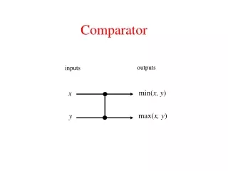
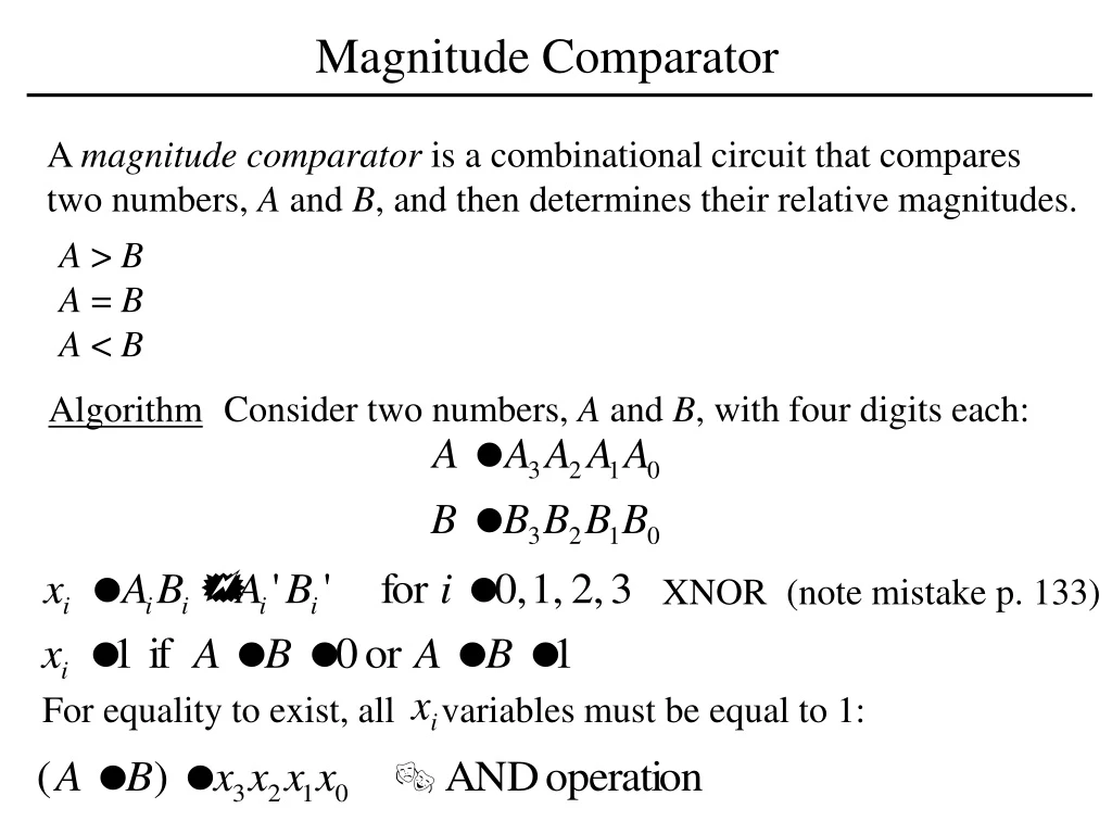
Magnitude Comparator. A magnitude comparator is a combinational circuit that compares two numbers, A and B , and then determines their relative magnitudes. A > B A = B A < B. Consider two numbers, A and B , with four digits each:. Algorithm. XNOR (note mistake p. 133).

E N D
Magnitude Comparator A magnitude comparator is a combinational circuit that compares two numbers, A and B, and then determines their relative magnitudes. A > B A = B A < B Consider two numbers, A and B, with four digits each: Algorithm XNOR (note mistake p. 133) For equality to exist, all variables must be equal to 1:
Magnitude Comparator To determine if A is greater than or less than B, we inspect the relative magnitudes of significant digits. If the two digits are equal, we compare the next lower significant pair of digits. The comparison continues until a pair of unequal digits is reached. The sequential comparison can be expressed by: Compare:
DECODERS • A decoder is a combinational circuit that converts binary information • from n input lines to an 2n unique output lines. • Applications: • Microprocessor memory system: selecting different banks of memory. • Microprocessor I/O: Selecting different devices. • Microprocessor instruction decoding: Enabling different functional • units. • Memory: Decoding memory addresses (e.g. in ROM).
3-to-8-line DECODER Truth Table If the input corresponds to minterm mi then the decoder ouputi will be the single asserted output.
2-to-4-line DECODER with Enable Input The decoder is enabled when E = 0. The output whose value = 0 represents the minterm is selected by inputs A and B. The decoder is disabled when E = 1 D0 … D3 = 1 A Decoder with enable input is called a decoder/demultiplexer. Demultiplexer receives information from a single line and directs it to the output lines. Complemented outputs
A 4 x 16 DECODER • When w = 0, the top decoder is enabled and the bottom is disabled. • Top decoder generates 8 minterms 0000 to 0111, while the bottom • decoder outputs are 0’s. • When w = 1, the top decoder is disabled and the bottom is enabled. • Bottom decoder generates 8 minterms 1000 to 1111, while the top • decoder outputs are 0’s.
MULTIPLEXERS/DATA SELECTORS A multiplexer is a combinational circuit that selects one of many input lines (2n) and steers it to its single output line. There are (2n) and n selection lines whose bit combinations determine which input is selected.
4-to-1LINE MULTIPLEXER DESIGN In general, a 2n–to–1-line multiplexer is constructed from an n–to 2n decoder by adding to it 2n lines, one to each AND gate. 1 0
Function implementation using multiplexers Function with n variables and multiplexer with n – 1 selection Input variables x, y: Selection lines, S1 and S0 Variable z: Date line 0 Data lines 1,2,3: OR gates are included
Function implementation using 4x1multiplexer z z’ 0 1 x y
Function implementation using 8x1multiplexer • Complete the truth table from the SOP. • The first n – 1 variables in the table are applied to the • selection inputs of the multiplexer. • For each combination of the selection variables, we evaluate • the output as a function of the last variable. • 4. Apply these values to the data input in proper order.
Function implementation using 8x1 MUX note the order of input lines
Three State Gates A three-state gate is a digital circuit that exhibits three states: 0, 1 and a high-impedance (high z state). The high impedance state behaves as an open circuit. Because of this feature (high z state), a large number of three-state gate outputs can be connected to form a common line without endangering load effects.
Multiplexers with Three State Gates When EN = 0, decoder outputs are zero, and the bus lines are in high z state. When EN = 1, one of the three-state buffers will be active depending on the binary value in the select inputs of the decoder. Note that the two output connections can not be done with other gates.