Viewer’s notes ... to help you …
Viewer’s notes ... to help you …. At the bottom left of each page there is a page number, when the slide has finished an automated sequence a small star appears in the bottom right hand corner to indicate that the slide may be ‘advanced’ when you are ready. To run the presentation:

Viewer’s notes ... to help you …
E N D
Presentation Transcript
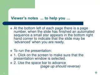
Viewer’s notes ... to help you … • At the bottom left of each page there is a page number, when the slide has finished an automated sequence a small star appears in the bottom right hand corner to indicate that the slide may be ‘advanced’ when you are ready. • To run the presentation: • 1. Click on the screen to make sure that the presentation window is selected. • 2. Use the space bar to advance (page up should reverse)
Introduction to the FP35 Kristina Frye Frye Electronics Modified for the UK by David Evans, Connevans Limited Thanks to Dr. Carol Sammeth, Ph.D. who wrote the original presentation that this one was based upon.
The FP35 offers: • Quick & accurate coupler measurement • An intuitive but versatile user interface • On-screen pop-up help windows • Multiple options for stimuli and measurement settings • Build-in thermal printer and RS232 capability
Standard Accessories Include: HA-1 & HA-2 couplers BTE adaptor Coupler microphone calibration adaptor
Optional Accessories Include: • Soft computer style carrying case
Optional Accessories Include: • External sound chamber
Basic analyzer features: • Automated IEC test sequence • Coupler Multicurve • Up to 4 response curves in dB Gain or dB SPL • Harmonic and intermodulation distortion • Three types of pure-tone sweeps • pure tone sweep audio demonstration • Ability to set custom default settings
Composite Option features: • Composite: Broadband signal consisting of 79 different frequencies presented simultaneously, updating up to five times a second - audio demonstration • Digital Speech: Modulated Composite signal for testing digital hearing aids with noise suppression technology - audio demonstration • ICRA, ANSI, LTASS (DSL) speech weighting options with Composite & Digital Speech
Basic Operation Print Help Reset “Operate” (On) Function Keys [F1] to [F5]
Basic Operation Exit Menu Back Next “Arrow” Keys Start/Stop
Front-panel Buttons to remember • [MENU] : Enters/exits local menus • [NEXT/BACK]: Moves between related measurement screens and between main & advanced menus • “Arrow” keys: Moves cursor through choices, or to adjust frequency/level • [START/STOP]: Starts/stops selected function • [EXIT] : Exits current screen, keeping curves • [RESET]: Exits and clears data, resetting analyzer
Function Keys – F1 through F5 • Function keys vary from screen to screen but are always labeled above the F key • e.g. pressing [F2] in the Opening screen takes you to the “Real Ear Audiogram” screen if available. F1 F2 F3 F4 F5
Function Keys (Continued) • Holding down a key will offer a pop-up menu - use arrows and ‘START’ to select • Repeated presses rotate through selections • e.g. in the Coupler Multicurve screen, [F4] selects the source type for measurement F4
Local Menus • Every measurement screen has a local menu containing settings for that screen • Shown here is the local menu for the coupler Multicurve screen
Additional Menu Choices • Some screens have additional menu choices. Use [NEXT] and [BACK] to move between the menus. • Shown here is the first of two advanced menus in the Coupler Multicurve screen
Onscreen Help • Pop-up help windows can guide you through steps available in the current screen • Shown here are help steps for the Real-Ear Audiogram Entry screen if available
Coupler Configurations Overview of testing a BTE
Proper Setup for Testing a BTE Velcro in the sound chamber and on the coupler assists in keeping the unit in place during measurement - centre the BTE microphone over the loudspeaker. HA-2 coupler with BTE adaptor.
Proper Set-Up for Testing an ITE Be sure “leaks” are sealed, or will have excessive 500 Hz gain
ANSI S3.22-1996 • For quality control to ensure dispensed hearing aids match manufacturer’s specs • Compared to previous standard it offers: • Multiple I/O and attack/release measurements • AGC aids tested at reduced reference test gain • From the Opening Screen, press [F5] or [F4]
Reminder: Level the sound chamber daily, or if room noise changes. ANSI ‘96 Setup Press [MENU] to open local menu. Use arrow keys to make selections. F1: Choose Aid Type F2 & F3: Select I/O freq to test
ANSI-’96 Results (AGC Aid) Average & Max Output Full On & Ref Test Gains Output (OSPL90) Curve Eq. Input Noise Frequency Range Frequency Response Curve Harmonic Distortion
ANSI-’96 Results (AGC Aid continued) Input/Output Curves I/O Curves Key
Coupler Multicurve Screen • Choose stimulus of pure tone (sweeps or single frequency), Composite, or Digital Speech • Measure/display a family of up to 4 frequency response curves • Show graph or data numerical values • Measure/display harmonic and intermodulation distortion
Coupler Multicurve Screen Amplitude F1– Delete curve F5 - Level F3 – Turn curve on/off F2 – Select curve F4 – Select source type
Coupler Local Menus A useful option in the local ‘MENU’ is to switch between Gain and SPL display. A second ‘Advanced’ menu is accessed using ‘Next’ key.
Family of Curves This curve family shows steady compression from 50 dB through 90 dB SPL Curve box Pressing ‘help’ explains the abbreviated curve codes
Another Family of Curves This curve family shows no compression between 50 and 80 dB SPL
Testing Digital Aids • Some DSP aids have NR circuitry that reduces gain when the input signal is noise • The composite signal, because it is continuous and non-modulating, is seen by the circuitry as “noise” • Thus, gain is reduced in the aid while the composite signal is on, and thus the measurement is not accurate
A Solution: The “Digital Speech” Signal • Switches Composite signal on/off intermittently in bursts • The “on” time can be set from 50 to 150 msec and the “off” time is randomly varied between 100 msec and 300 msec • Thus, the hearing aid responds as if the input is speech instead of noise (i.e., modulated instead of continuous) • ANSI, ICRA, and LTASS speech weightings are available with this stimulus too
Numerical Data Display To display numerical data select DATA in the DATA/GRAPH selection in the local menu
Harmonic Distortion Test Harmonic distortion can be measured during any pure-tone sweep by setting the DISTORTION type in the local menu to 2ND, 3RD, or TOTAL. Distortion scaling on right side of graph
Intermodulation Distortion Test IM distortion can be measured by setting the IM FREQ DIFF in the advanced menu. This will create the DIST source type selection F4 – Select DIST type
Example using DSP Aid ICRA Spectra ANSI Spectra Composite Signal
CIC Option CIC coupler Set the COUPLER TYPE to CIC in the local menu. HA-1 coupler
FP35 Real-ear use Click here to jump past real-ear information
The FP35 real ear version Basic: Probe/ref microphones and ear hook Calibration adaptors Extension pole for speaker
The FP35 real ear version options: • Child-sized ear hook for real-ear measurements • Swing-arm speaker • Insert earphones and calibration adaptor
Real-Ear Option features: • Fitting rules: NAL-NL1, DSL Linear, DSL WDRC, NAL-RP, plus the traditional ones • Age correction factors for testing kids with NAL-NL1 and DSL • Insertion Gain & SPL-o-gram methods • Coupler Target & Simulated Real-ear NEW • RECD
FP35 Real-ear Screens • Audiogram entry screen • Real-ear SPL screen • Unaided & aided screen • Insertion gain screen Use the [NEXT] and [BACK] keys when in Real-ear Mode to cycle between these four screens.
Audiogram Entry Screen Amplitude Frequency F3 – Generate Target F2 – Select HTL/UCL/Bone
Features • Fitting rules: NAL-NL1, DSL Linear, DSL WDRC, NAL-RP, plus the traditional ones • Age correction factors for testing kids with NAL-NL1 and DSL • RECD
NAL-NL1 Features • Age of client (kids) • Number of channels • Bone conduction • Bilateral vs. Unilateral loss • Limiting: Multi-channel or Wideband • Compression threshold
Generating the Selected Target • Press [F3] to generate the target • Press [F5] to toggle between IG target and SPL target • Shown here is IG Target Marked 30 mm from the Tip for Adults and 25 mm for children Inter- F3 F5
Set-up for Real Ear Measures • Internal sound chamber converts to sound field speaker; should be ear height • Recommend position patient 12” from the speaker at 45° angle • Stand away from the patient/loudspeaker during measurements Probe
Proper Placement of Microphones Ref Mic Above the Pinna Marked 30 mm from the tip for Adults and 25 mm for children Inter-Tragal Notch Probe Mic
Leveling the Sound Field Loudspeaker • Position patient and earhook/ref mic (probe tube insertion not required) • Press “Level” [F5] • Success: a straight line and indication that system was leveled Reminder: Re-level for each patient and each ear
Real-ear SPL Screen UCLs Target HTLs F2 – Select Curve F4 – Select Source Type