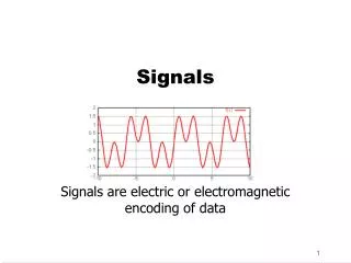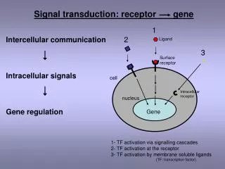
Communication Signals
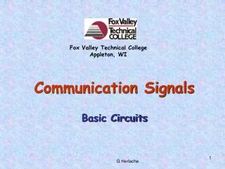
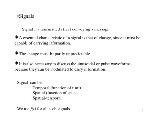
Fox Valley Technical College Appleton, WI. Communication Signals. Basic Circuits. Pictorial Diagram of A Simple Electric Circuit. Current Flow. Wire Conductor. Voltage Source. -. +. Lamps. Battery. A Schematic Diagram for the Simple Circuit. Battery Or DC Voltage Supply. PL2.

Communication Signals
E N D
Presentation Transcript
Fox Valley Technical College Appleton, WI Communication Signals Basic Circuits
Pictorial Diagram of A Simple Electric Circuit Current Flow Wire Conductor Voltage Source - + Lamps Battery
A Schematic Diagram for the Simple Circuit Battery Or DC Voltage Supply PL2 VS PL1 Lamps
Hardware Pictorial and Schematic of a Closed CircuitUsing a SPST switch for control Off On Closed Switch - + V I - + Closed Circuit Path => Current Flows
Hardware Pictorial and Schematic of an Open CircuitUsing a SPST switch for control Off On Open Switch - + V - + Broken Circuit Path => NO Current Flow
Example: Pictorial of a SPDT switch controlling two lamps 1 Lamp 1 2 + Switch - Lamp 2
Example: Schematic of a SPDT switch controlling two lamps 1 1 SW SW Lamp 1 Lamp 1 2 2 - + - + V V Lamp 2 Lamp 2
Switch Symbols NCPB NOPB SPST-NC SPDT Break-Make PB SPST-NO Single-pole rotary (6-position) DPST DPDT
Chassis Ground DC Ground AC Ground Symbols for Ground
A Simple Circuit Schematic Using Ground Symbols I - + 12 V 0 V Ground Symbol
V A Ω T Schematic Symbols Introduced So Far Circuit Breaker Fuse Grounds Rheostat Potentio- meter Battery Resistor Lamps SPST-NO SPST-NC NOPB NCPB SPDT Break-Make PB DPST Ammeter Voltmeter Ohmmeter Photo Resistor Thermistor DPDT Rotary Switch
Watch the video clip and see if you can tell what kind of circuit this is! http://www.teachertube.com/view_video.php?viewkey=9c7de745bd6b6d1a7a86
Series Circuit IS + V3 − +V1− +V2− IS VS + V4 − +V6− +V5− IS • One path for current. So all components have the same current through them. • But components have different voltages consistent with the voltage – current relationship for each type of component.
Watch the video clip and again, see if you can tell what kind of circuit this one is. http://www.teachertube.com/view_video.php?viewkey=318031eedd5700a8d3d2
Parallel Circuit I1 I2 I3 I4 I5 + VS − + VS − + VS − + VS − + VS − VS • One voltage source. So all components have the same voltage across them. • But the components have different currents consistent with the voltage – current relationship for each type of component.
Series-Parallel Circuit VS Most circuits are a combination of series and parallel circuits.