Single-molecule force microscope
Single-molecule force microscope. All biological motion, from cellular motility to replication and segregation of DNA, is driven by molecular-scale forces

Single-molecule force microscope
E N D
Presentation Transcript
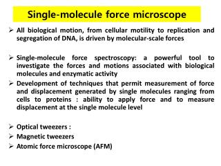
Single-molecule force microscope All biological motion, from cellular motility to replication and segregation of DNA, is driven by molecular-scale forces Single-molecule force spectroscopy: a powerful tool to investigate the forces and motions associated with biological molecules and enzymatic activity Development of techniques that permit measurement of force and displacement generated by single molecules ranging from cells to proteins : ability to apply force and to measure displacement at the single molecule level Optical tweezers : Magnetic tweezers Atomic force microscope (AFM)
Advantage of single-molecule techniques • Avoid problems associated with population averaging inherent in ensemble measurements. • Rare or transient phenomena that would otherwise be obscured by averaging can be resolved provided that the measurement technique has the required resolution and that the events can be captured often enough to ensure that they are not artifactual.
Applications • Motor proteins such as kinesins and myosins: The step size, stall-force force and processivity • Measurement of RNA polymerase advancing a single base pair (0.34 nm) along DNA the mechanical • Disruption of covalent bonds (nanonewton forces) • Assay of nucleic acid folding kinetics (~0.1 pN). • Manipulation of single cells (~100 μm) to probe the strength and location of receptor binding and adhesion or to measure traction and adhesion forces • Viscoelastic properties : force-extension relationship of individual polymers, in particular of nucleic acids • Analysis of ligand and antibody binding • Multistate unfolding of single proteins and nucleic acid structures
Molecule attachment • One end of the molecule under study is attached to a surface, and the free end is attached to a probe- an optically trapped bead, magnetic bead or AFM tip-through which force is applied • Covalently modified nucleotides containing a carbon spacer arm terminated in a reactive moiety : labeling nucleic acids at their ends • Ligand-receptor pairs such as biotin-avidin or antibody-antigen pairs : tight binding to the surface and to the probe. • Proteins : tags such as biotin and hexahistidine, or cysteine residues • Non-specific binding: artifacts and uncertainty in the data - Use of inert proteins such as bovine serum albumin and non-ionic surfactants are used to passivate surfaces and probes.
Optical tweezers • Optical trap : the most versatile single-molecule manipulation technique. • Used to exert forces in excess of 100 pN on particles ranging in size from nanometers to micrometers • Measuring the three-dimensional displacement of the trapped particle with sub-nanometer accuracy and sub-millisecond time resolution. • Suitable for measuring force and motion
Optical trapping • Focused laser beam to a diffraction-limited spot with a high numerical aperture (NA) microscope objective :Light-gathering ability and resolution • Dielectric particles in the vicinity of the focus : three-dimensional restoring force directed toward the focus. • Dielectric particle is polarized by the optical field Interaction of optically induced dipole with the steep gradient near the focus of the laser A force directed along the gradient
NA: Dimensionless number that characterizes the range of angles over which the system can accept or emit light. - Lenses with larger numerical apertures collect more light and generally provide a brighter image NA = ɳ sin ɵ • ɳ is the index of refraction of the medium in which the lens is working • (1.0 for air, 1.33 for pure water, and up to 1.56 for oils) • - θ is the half-angle of the maximum cone of light that can enter or exit the lens
Dielectric objects are attracted to the center of the beam, slightly above the beam waist. • The force applied on the object depends linearly on its displacement from the trap center just as with a simple spring system. • Laser beams spread out as they propagate, but slowly. Far away from the narrowest part of the beam, the spread is roughly linear with distance—the laser beam forms a cone of light in the "far field”
The spring constant, or stiffness : steepness of the optical gradient (how tightly the laser is focused), the laser power, and the polarizability of the trapped object. • Particles ranging in size from ~20 nm to several micrometers can be stably trapped. • Single cells, organelles within cells, lipid vesicles and polystyrene or silica microspheres used alone or as probes linked to a molecule of interest.
Technical requirements • Trapping lasers : Gaussian output intensity profile to achieve the smallest focal spot producing the largest optical gradient • A trapping laser with superior pointing and power stability: Fluctuations in beam pointing spurious motions of the optical trap, force fluctuations increase in measurement noise. • Trapping lasers : Near infrared wavelengths (800–1,100 nm) minimize optically induced damage in biological specimens. • Biological applications the trapping laser : diode-pumped neodymium yttrium aluminum garnet (Nd:YAG) with a wavelength of 1,064 nm exceptional power and pointing stability, and output powers in excess of 10 W.
The NA of the trapping objective: at least 1.2 to achieve the steep focus needed to create a stable optical trap. Use of a water or oil immersion objective.
Detection of displacement • Means of non-invasively manipulating objects in solution. simultaneous measurement of displacement and force • Back-focal plane (BFP) interferometry: The most versatile and sensitive method Interference between light scattered by the trapped bead and unscattered light to measure the three-dimensional position of the bead relative to its equilibrium position. • Measurement of interference: a quadrant photodiode or position-sensitive detector placed in a plane optically conjugate to the BFP of the condenser: BFP of the condenser is imaged onto the quadrant photodiode or position-sensitive detector. • The detectors are sensitive to minute intensity asymmetries in the interference pattern
Back-focal plane (BFP) interferometry • Light pattern at the back-focal-plane of the condenser • When the size of the bead is smaller than the wavelength of the laser, the sample behaves as a dipole. Light passing through the microsphere is scattered New spherical wave. Light exiting the trap has two different contributions: - The light scattered by the bead - The light that do not interact with the bead. • Both terms are collected by the condenser and interfere at its back focal plane. • The images were recorded with a CCD camera placed at the BFP of the condenser. The interference clearly changes when the sample moves in the 'x' direction. • The front focal point of an optical system: any ray that passes through it will emerge from the system parallel to the optical axis. • The rear (or back) focal point of the system: rays that enter the system parallel to the optical axis are focused such that they pass through the rear focal point.
A trapped bead at its equilibrium position A symmetric interference pattern and a null detector signal • Displacement of the bead Asymmetric interference profile, generating a detector signal proportional to the bead displacement. • Axial motion of the trapped particle: changes in interference pattern changes in the total intensity at the detector. • Sub-nanometer spatial resolution and bandwidths in excess of 100 kHz • Implementation of BFP interferometry : interference from the scattered trapping laser, but it is sometimes more convenient to use a second low-power detection laser. • Tracking of the position of two trapped beads: - Splitting one laser into two beams based on polarization, - Use of two different detection lasers
Dynamic control of the trap position • Dynamic position control: A feedback loop to maintain a constant force on the trapped bead or to actively compensate for thermal drift. • Moving the trap : deflecting the laser beam with galvanometer or piezoelectric actuated mirrors or an acoustooptic deflector : ~10 μs time scale, and a few micrometers in a single axial plane. • Piezoelectric stage : move the trapping chamber with nanometer accuracy while keeping the trap position fixed : slower (~10 ms) response time, full three-dimensional control over a large range of motion (~100 μm).
Applications of optical tweezers • Specific interaction between the trapped object and a fixed partner and to measure the force and displacement resulting from the interaction • Measurement of the force and displacement of optically trapped kinesin-coated beads moving along fixed microtubules • Binding probability and unbinding force were measured for virus-coated beads brought into contact with erythrocytes • Binding strength and activation state of single fibrinogen-integrin pairs was measured on living cells
Kinesine • Motor proteins in eukaryotic cells • Heterotetramericfast axonal organelle transport motor consisting of 2 identical motor subunits • Move along microtubule filaments, and are powered by the hydrolysis of ATP (thus kinesins are ATPases). • Movement of kinesinsin cellular functions - Mitosis, meiosis and transport of cellular cargo, such as in axonal transport. • Walk towards the plus end of a microtubule, which, in most cells, entails transporting cargo from the centre of the cell towards the periphery : Anterograde transport.
Microtubule • Component of the cytoskeleton, • Cylindrical polymers of tubulin: Can grow as long as 25 micrometers and are highly dynamic. • Outer diameter of microtubule : 25 nm. • Important for maintaining cell structure, providing platforms for intracellular transport, forming the mitotic spindle, as well as other cellular processes
Measurement of the force and displacement of optically trapped kinesin-coated beads moving along fixed microtubules. One bead is captured in the optical trap formed near the focus of an infrared laser (pink). The assay consists of bringing the trapped bead to the microtubule (brown tube) attached to the surface of the trapping chamber. Measurement of translocation and force generation of individual RNA polymerase molecules as they transcribe DNA. An RNA polymerase molecule (purple) is attached to an optically trapped bead, and the free end of the DNA template is attached to the surface of the trapping chamber. As the DNA is transcribed, the bead is pulled along the DNA by the polymerase. By moving the stage to compensate for this motion, thereby keeping the bead at the same position in the optical trap, long transcriptional records can be obtained at a constant force. Stall force (~30 pN), transcriptional pausing, backtracking of the polymerase along the DNA template and the mechanism of polymerase translocation
The dumbbell assay: Free end of the DNA is attached to a second bead, which is held in a second, independent, optical trap. • The force on the bead is kept constant by moving one of the traps
Magnetic tweezers • Most straightforward of the three techniques to implement • A pair of permanent magnets placed above the sample holder of an inverted microscope outfitted with a charge-coupled device (CCD) camera linked to a frame grabber. • Magnetic manipulation: single-molecule technique that permits controlled application of torque and force on a biomolecule. • Exerting forces in excess of 1 nN (electromagnetic tweezers), and can be used to rotate magnetic particles ranging from 0.5 to 5 μm. • Ideally suited to the study of nucleic acid enzymes, particularly DNA topoisomerases and the rotary motor F0F1 ATPase
Technical requirements and calibration • Neodymium iron boron (Nd2Fe14B) magnets : NIB or simply neodymium magnets - The strongest permanent magnets with magnetic fields : ~ 1.3 tesla. • Classified by the magnetic energy density in units of megagauss-oersteds. • The highest energy density magnets: range of N45–N50. • Magnets measure a few millimeters on each side and are configured with the north pole of one magnet facing the south pole of the other, separated by a ~1 mm gap. • Magnetic field strength decreases roughly exponentially with a characteristic length scale comparable to the separation between the magnets. Force on the magnetic particle changes in proportion to displacement with a characteristic length scale of 1 mm: Effective stiffness : ~ 10−6pNnm –1 The change in force on a magnetic particle that moves a full 10 μm:~ 0.01 pN
Insensitive to drift and noise in the position of the magnets, which considerably relaxes the design constraints on the magnet translation and rotation mechanisms. • Magnetic tweezers based on permanent magnets : well-suited for constant force experiments, but they cannot be used to manipulate magnetic particles in three dimensions. • Constant one dimensional pulling force without a local minimum
A surface-immobilized DNA molecule is attached to a micron sized super-paramagnetic bead. • Permanent magnets placed above the sample chamber induce a magnetic moment in the magnetic bead, which experiences a force due to the magnetic field gradient of the magnets. • Force is controlled by changing the distance between the magnets and the sample cell. • The magnetic bead can be rotated by rotating the permanent magnets. • This permits precise control over the linking number and topology of a single DNA molecule.
Attachment of a super-paramagnetic bead (green) to the surface of the trapping chamber • by a single molecule of DNA. • Magnetic field gradient (dashed lines) along the axial direction using a pair of small permanent magnets (red and blue) above the trapping chamber. • The force is controlled by moving the magnets in the axial direction (bidirectional arrow). • Rotation of the magnetic bead (red circular arrow) with a one-to-one correspondence • by rotation of the magnets (black circular arrow). • Real-time position tracking by a microscope objective (gray) image of the bead using a • CCD camera.
To measure DNA topology with magnetic tweezers, extension is measured as a function of rotation for a 1 μm super-paramagnetic bead tethered to a surface by a 3-kb molecule of DNA under 0.4 pN of pulling force. • As the DNA is over- or under-wound (supercoiled), there is a slight decrease in extension near zero turns, which is due to the accumulation of twist in the DNA molecule. • At ± 4 turns the DNA buckles, forming a plectoneme loop. Each subsequent turn increases the plectonemeby another loop, leading to a linear decrease in extension from 4 to 12 turns. • Removal of the plectonemes by the activity of a topoisomerase can be directly observed in real time by monitoring the extension of a supercoiled DNA molecule.
DNA supercoiling • Over- or under-winding of a DNA strand. • Important in a number of biological processes, such as compacting DNA. • Topoisomerases : change DNA topology to facilitate functions such as DNA replication or transcription. • Plectoneme :A loop of helices (especially of nucleic acid) twisted together
A double-stranded DNA molecule is fixed with multiple binding sites on one end to a glass surface and on the other to a magnetic micro bead • By turning the magnets, torsional stress can be applied to the DNA molecule. Rotations in the sense of the DNA helix are counted positively and vice versa. • While twisting, the magnetic tweezers also allow stretching the DNA molecule. This way, torsion extension curves may be recorded at different stretching forces. • For low forces (less than about 0.5 pN), the DNA forms supercoils, so called plectonemes, which decrease the extension of the DNA molecule quite symmetrically for positive and negative twists. • Augmenting the pulling force already increases the extension for zero imposed torsion. Positive twists lead again to plectoneme formation that reduces the extension. Negative twist, however, does not change the extension of the DNA molecule a lot. This can be interpreted as the separation of the two strands which corresponds to the denaturation of the molecule. In the high force regime, the extension is nearly independent of the applied torsional stress. The interpretation is the apparition of local regions of highly overwound DNA. An important parameter of this experiment is also the ionic strength of the solution which affects the critical values of the applied pulling force that separate the three force regimes