Download
1 / 14
140 likes | 241 Vues
Explore a virtual environment where parts collide, animate, and assemble with realistic movement. Utilize Virtual Author for efficient animations and segmentation tasks. Develop skills in assembly processes and symmetry application.

E N D
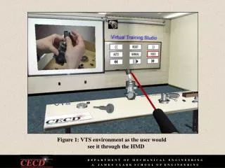
Figure 1: VTS environment as the user would see it through the HMD
Figure 2: Two colliding parts become translucent, but movement is not restricted.
Figure 3: Parts are being animated dropping down on the table. Random positions were automatically generated by Virtual Author.
Figure 4: Instructor’s view of the virtual environment run by Virtual Author
Figure 5: Virtual demonstration of attachment of engine cover to top of engine case
Figure 6: Segmentation performed on model airplane engine piston
Figure 7: Segmentation performed on a parachute deployment device cartridge
Figure 8: An example of subtype B4 symmetry where the pin can be inserted from two different positions (either side of the piston hole). For each position either the alternate or the primary orientation around the secondary axis may be used.
Figure 9: Animation of nut sliding onto threaded crankshaft rod can be made more efficient by taking advantage of the symmetry of the nut around the main axis (axis of the nut cylinder).
Figure 10: Placement of propellant grain at its alternate position
Figure 14: Rubber o-ring must be rolled on top of the rightmost rectangular groove.
Figure 15: Detailin the form of flashing arrows is added to animation of small cap attachment to nozzle.


![Figure 9.1 Flow graph of 1 st -order complex recursive computation of X [ k ].](https://cdn3.slideserve.com/5826681/figure-9-1-flow-graph-of-1-st-order-complex-recursive-computation-of-x-k-dt.jpg)