Download
1 / 12
120 likes | 338 Vues
Determining Optical Properties of Uranium Oxide. Richard Sandberg Brigham Young University Special Thanks to Kristi Adamson, Shannon Lunt, Elke Jackson, Dr. David Allred, Nathan Orton, Mike Diehl, Dr. Steven Turley. Why study Uranium Oxide?. David D. Allred: Slide 2 . 1. Image:

E N D
Determining Optical Properties of Uranium Oxide Richard Sandberg Brigham Young University Special Thanks to Kristi Adamson, Shannon Lunt, Elke Jackson, Dr. David Allred, Nathan Orton, Mike Diehl, Dr. Steven Turley
Why study Uranium Oxide? • David D. Allred: • Slide 2. • 1.Image: • a.About 5 years ago my research group was asked to design, deposit and characterize a ML reflector coating for a troika of mirrors for the Image spacecraft’s EUV instrument. It is in orbit now in a polar orbit and produces images of the earth’s magnetosphere like the one shown here, taken from a distance of about 20,000 Km above the North Pole. The small central circle is the earth’s aurora. The gauzy structure, reddish here in false color is the true subject of the instrument. He +1 ions caught in the earth’s magnetic field can resonantly scatter 41 eV light from the sun’s corona. 41 eV corresponds to the brightest line Helium +1 ions can emit: the 2p to 1s transition. • b.Ordinary mirrors don’t reflect 41 eV well. No single surface mirror reflects well in the EUV so people use ML mirrors. They can have high reflectivity (20 to 70% at normal incidence depending on the materials and wavelengths. • c.Incidentally, in addition to Space, applications in medicine and microelectronic (EUV lithography) are being investigated. [EUV lithography should be over 1 B$ in 5-6 years] • BUT why Uranium? Computations by our group showed that URANIUM was one of the best materials for the IMAGE application. However, U is chemically active and very subject to oxidation. My group couldn’t stop the surface oxidation of the mirror so they created a design that uses the U oxide that naturally forms on the top of the ML as a key part to the OPTICAL Performance of the ML. • Now my group is examining whether we can use U oxide in its own right as an EUV materials. • IMAGE Satellite Mirror Project • High Theoretical Reflectivity • Applications: Medical Equipment • Space Observation • Lithography
David D. Allred: 1.Examining whether we can deposit the uranium already as an oxide. Reasons why a.The layer may be smoother if deposit as an OXIDE already. Oxidation produces a buckled surface. It is harder to get optical constants (n and k) if their surface isn’t smooth. b. We need the OC if we are to design optical devices. c.The O C I will talk about today mostly in visible and UV but these will help us get to EUV constants and help us determine thickness of layers. And to know of the d.Stability of surfaces in air. – [I can report right now UO2 formed isn’t completely stable but much more than U. Probably comparable to Mo] e.Important to get if we are do to opt. devices. HOW 2.Tell what’s on the slide, Creating our samples • Reactive DC Magnetron Sputtering • Creates a uranium oxide film • We create samples with thickness of 15–30 nanometers
Characterizing Samples • David D. Allred: • SLIDE 4: Characterization. • The slide does it for first 2. • Last 2 XPS and ellipsometry main subject today. • It turns out that ellipsometry is very sensitive to valence, as you will see. We are going to have more to report on this than we planned 1 year ago. Why these tools? • X-Ray Diffraction- thickness • Atomic Force Microscopy-thickness & roughness • X-Ray Photoelectric Spectroscopy- chemical state • Ellipsometry- thickness & valence state
David D. Allred: Determining Composition With XPS • Peaks indicate electron binding energy • Peaks shift with varying oxidation states
David D. Allred: SLIDE 6: Ellipsometry Polarized light hits sample. Reflects elliptically polarized light. This is then analyzed to get relative ratio of p to s polarization and the angle of rotation of the ellipse. One of the strengths of ellipsometry is that only ratios are required. There are 2 ratios: Delta and Psi. Ellipsometry • Polarized light hits sample • Reflects elliptically polarized light
Finding Constants From Ellipsometry • David D. Allred: • SLIDE 7: Finding Constants from Ellipsometry • Point 1. Mention that this is spectroscopic ellipsometry. Delta and Psi are measured in a few seconds at about 450 wavelengths in a few seconds. And you can use many angles. So get several thousand pieces of data used to find thickness, and n and k as function of Energy. But thicknesses are only accurate if N and k are fairly well known. There can be some noise in the apparent n and K. A better way is parameterize the functions so that 3-4000 data determine 15 or so constants. • You need a model. Lorentz is one that we used. • Since we need n and k to get Thickness. • Point 2. We wanted to compare what we found with past. But… go on with the slide. • Lorentz Oscillator models were used to extract reflectance and n and k • Ellipsometry Limitations • Comparison to Literature • They used bulk samples, we use thin films • We know our layers are hybrid of different layers
David D. Allred: SLIDE 8: Band model Usually when our group has used ellipso to get thickness of a thin film it has been relatively straightforward. But not so for UO2. There are still 2 electrons in U that are not involved in Chem- bonding. These electrons produce states in the gap of the oxide UO2. The reason I have this diagram is to show this. We also learned that UO2 can tolerate considerable nonstoichiometry. Really it is UO(2+x). As the x changes, k, and to a lesser extent, n changes Suggestion of Band Model for UO2 (D: Electron density of states) From Naegele et al 1976
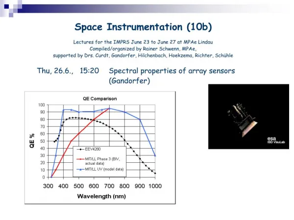
David D. Allred: Slide 9 (Reflectances) N and k are not available in the literature for all U oxide compositions so we have converted n and k to reflectances. Calculated reflectances. Reflectances are more known. Reflectances are normal incidence. Directly down on the samples. We plot R versus Energy. Sample 2 was sputtered with very little oxygen. It is mostly U metal. That is why its reflectance is high on the right hand side; the reflectances of metals are high in the IR. The right hand side is about .8 eV which is 1.5 microns in IR. UV starts at 3 eV. Now LOOK at the positions of the maxima. 3.5 eV for sample 1 and 6 eV for 4. Remember these. Reflectance of Our Samples Sample 1 Sample 2 Sample 3 Sample 4
David D. Allred: Slide 10 (Reflectances from the literature.) LOOK at the maxima. 4.3 eV for 2.25 and 5.3 eV for 2. Now look at the low energy side. About 12-13%. Now go back to slide 9. See here only 1 stays as high at these two from literature at low energy. [The peaks in the calculated R for 3 and 4 may be real or they may be artifacts of the Lorentz oscillators. They could be real. Recall that as the composition of the oxide changes the maxima change position. Our samples could be layered. ] In any case we note that our samples really are different than Literature. We have done enough work to trust our data.
Further Research Depth Profiling At-wavelength reflection measurements Monochrometer Longer time scale for oxidation David D. Allred: Slide 11. 1. 2. Stress that we are ready now to do EUV measurements.
Thank you Richard Sandberg Brigham Young University E-mail rls62@email.byu.edu Phone (801) 368-7779