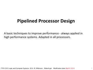
Pipelined Processor Design
Explore the benefits of pipelining in processor design, from laundry examples to real-life applications, and understand pipeline hazards, control, and data forwarding. Compare serial execution to pipelining and learn about clocked synchronous pipelines and pipeline performance metrics. Dive into a MIPS processor pipeline and examine the single-cycle versus pipelined performance for enhanced efficiency.


Pipelined Processor Design
E N D
Presentation Transcript
Pipelined Processor Design ICS 233 Computer Architecture & Assembly Language Prof. Muhamed Mudawar College of Computer Sciences and Engineering King Fahd University of Petroleum and Minerals
Presentation Outline • Pipelining versus Serial Execution • Pipelined Datapath and Control • Pipeline Hazards • Data Hazards and Forwarding • Load Delay, Hazard Detection, and Stall • Control Hazards • Delayed Branch and Dynamic Branch Prediction
A B C D Pipelining Example • Laundry Example: Three Stages • Wash dirty load of clothes • Dry wet clothes • Fold and put clothes into drawers • Each stage takes 30 minutes to complete • Four loads of clothes to wash, dry, and fold
30 30 30 30 30 30 30 30 30 30 30 30 D A B C Sequential Laundry • Sequential laundry takes 6 hours for 4 loads • Intuitively, we can use pipelining to speed up laundry 6 PM 7 8 9 10 11 12 AM Time
30 30 30 30 30 30 30 30 30 30 30 30 C D A B Pipelined Laundry: Start Load ASAP • Pipelined laundry takes 3 hours for 4 loads • Speedup factor is 2 for 4 loads • Time to wash, dry, and fold one load is still the same (90 minutes) 6 PM 7 8 9 PM Time
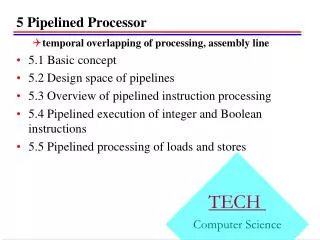
… … … … … … 1 1 1 1 1 1 2 2 2 2 2 2 k k k k k k Serial Execution versus Pipelining • Consider a task that can be divided into k subtasks • The k subtasks are executed on k different stages • Each subtask requires one time unit • The total execution time of the task is k time units • Pipelining is to overlap the execution • The k stages work in parallel on k different tasks • Tasks enter/leave pipeline at the rate of one task per time unit Without Pipelining One completion every k time units With Pipelining One completion every 1time unit
S1 S2 Sk Input Output Register Register Register Register Clock Synchronous Pipeline • Uses clocked registers between stages • Upon arrival of a clock edge … • All registers hold the results of previous stages simultaneously • The pipeline stages are combinational logic circuits • It is desirable to have balanced stages • Approximately equal delay in all stages • Clock period is determined by the maximum stage delay
nk Serial execution in cycles Sk Sk → k for large n = = Pipelined execution in cycles k + n – 1 Pipeline Performance • Let ti = time delay in stage Si • Clock cycle t = max(ti) is the maximum stage delay • Clock frequencyf = 1/t = 1/max(ti) • A pipeline can process n tasks in k + n – 1 cycles • k cycles are needed to complete the first task • n – 1 cycles are needed to complete the remaining n – 1 tasks • Ideal speedup of a k-stage pipeline over serial execution
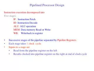
MIPS Processor Pipeline • Five stages, one cycle per stage • IF: Instruction Fetch from instruction memory • ID: Instruction Decode, register read, and J/Br address • EX: Execute operation or calculate load/store address • MEM: Memory access for load and store • WB: Write Back result to register
IF IF Reg Reg ALU ALU MEM MEM Reg Reg 900 ps 900 ps Single-Cycle vs Pipelined Performance • Consider a 5-stage instruction execution in which … • Instruction fetch = ALU operation = Data memory access = 200 ps • Register read = register write = 150 ps • What is the clock cycle of the single-cycle processor? • What is the clock cycle of the pipelined processor? • What is the speedup factor of pipelined execution? • Solution Single-Cycle Clock = 200+150+200+200+150 = 900 ps
IF Reg ALU MEM Reg IF Reg ALU MEM Reg IF Reg ALU MEM Reg 200 200 200 200 200 200 200 Single-Cycle versus Pipelined – cont’d • Pipelined clock cycle = • CPI for pipelined execution = • One instruction completes each cycle (ignoring pipeline fill) • Speedup of pipelined execution = • Instruction count and CPI are equal in both cases • Speedup factor is less than 5 (number of pipeline stage) • Because the pipeline stages are not balanced max(200, 150) = 200 ps 1 900 ps / 200 ps = 4.5
Pipeline Performance Summary • Pipelining doesn’t improve latency of a single instruction • However, it improves throughput of entire workload • Instructions are initiated and completed at a higher rate • In ak-stage pipeline, k instructions operate in parallel • Overlapped execution using multiple hardware resources • Potential speedup = number of pipeline stagesk • Unbalanced lengths of pipeline stages reduces speedup • Pipeline rate is limited by slowest pipeline stage • Unbalanced lengths of pipeline stages reduces speedup • Also, time to fill and drain pipeline reduces speedup
Next . . . • Pipelining versus Serial Execution • Pipelined Datapath and Control • Pipeline Hazards • Data Hazards and Forwarding • Load Delay, Hazard Detection, and Stall • Control Hazards • Delayed Branch and Dynamic Branch Prediction
ALU result Data Memory 0 0 0 0 1 1 1 Address 1 Data_out Data_in 32 32 32 32 00 E PC Single-Cycle Datapath • Shown below is the single-cycle datapath • How to pipeline this single-cycle datapath? Answer: Introduce pipeline register at end of each stage Jump or Branch Target Address Beq J Bne 30 +1 Imm26 Imm16 PCSrc zero Instruction Memory Registers 32 Rs 5 BusA RA A L U 30 32 IF = Instruction Fetch ID = Decode & Register Read EX = Execute MEM = Memory Access WB = Write Back Instruction Rt 5 RB BusB Address 32 Next PC RW Rd BusW RegDst Reg Write clk Mem Read Mem Write Mem toReg ExtOp ALUSrc ALUCtrl
Data Memory 0 0 0 1 1 1 Address Data_out Data_in 32 32 32 32 E Pipelined Datapath • Pipeline registers are shown in green, including the PC • Same clock edge updates all pipeline registers, register file, and data memory (for store instruction) zero IF = Instruction Fetch ID = Decode & Register Read EX = Execute MEM = Memory Access 32 WB = Write Back NPC2 Next PC NPC +1 Imm Instruction Imm26 BusA ALU result ALUout WB Data RA Imm16 A L U Register File A RB Instruction Memory BusB 5 Rs D RW BusW 1 Instruction Rt 5 B 0 Address PC Rd clk 32
Data Memory 0 0 0 1 1 1 Address Data_out Data_in 32 32 32 32 E Problem with Register Destination • Is there a problem with the register destination address? • Instruction in the ID stage different from the one in the WB stage • Instruction in the WB stage is not writing to its destination register but to the destination of a different instruction in the ID stage zero ID = Decode & Register Read 32 IF = Instruction Fetch EX = Execute MEM = Memory Access NPC2 WB = Write Back Next PC NPC Imm Instruction +1 BusA Imm26 ALUout WB Data RA ALU result A L U Register File Imm16 A RB Instruction Memory BusB D RW 5 Rs BusW 1 Instruction B Rt 5 0 Address Rd PC clk 32
Data Memory 0 0 1 1 Address Data_out Data_in 32 32 32 32 E Pipelining the Destination Register • Destination Register number should be pipelined • Destination register number is passed from ID to WB stage • The WB stage writes back data knowing the destination register zero IF ID EX MEM WB 32 Next PC NPC2 +1 Imm26 NPC ALU result Imm Instruction Imm16 BusA ALUout WB Data RA Instruction Memory A L U Register File A 5 RB Rs BusB Instruction Rt 5 D RW BusW 1 0 Address Rd B PC Rd4 Rd3 1 0 Rd2 32 clk
Reg Reg Reg Reg IM DM IM IM IM IM Graphically Representing Pipelines • Multiple instruction execution over multiple clock cycles • Instructions are listed in execution order from top to bottom • Clock cycles move from left to right • Figure shows the use of resources at each stage and each cycle Time (in cycles) CC4 CC5 CC6 CC7 CC8 CC2 CC3 CC1 lw $t6, 8($s5) Reg Reg Reg Reg ALU add $s1, $s2, $s3 DM ALU Program Execution Order DM ori $s4, $t3, 7 ALU Reg sub $t5, $s2, $t3 DM ALU sw $s2, 10($t3) DM ALU
Up to five instructions can be in the pipeline during the same cycle Instruction Level Parallelism (ILP) ALU instructions skip the MEM stage. Store instructions skip the WB stage ID EX MEM WB lw $t7, 8($s3) lw $t6, 8($s5) IF ID EX MEM WB Instruction Order IF ID EX – ori $t4, $s3, 7 WB IF ID EX – WB sub $s5, $s2, $t3 sw $s2, 10($s3) IF ID EX MEM • Time • CC1 • CC2 • CC3 • CC4 • CC5 • CC6 • CC7 • CC8 • CC9 Instruction-Time Diagram • Instruction-Time Diagram shows: • Which instruction occupying what stage at each clock cycle • Instruction flow is pipelined over the 5 stages IF –
Data Memory 0 0 1 1 Address Data_out Data_in 32 32 32 32 E Control Signals IF ID EX MEM WB J Next PC Beq zero +1 Bne Imm26 ALU result Imm16 32 PCSrc Instruction Memory 5 Rs NPC2 Instruction Rt 5 Address NPC Rd PC Imm Instruction BusA ALUout WB Data RA A L U 32 Register File A RB BusB D RW BusW 1 0 B Rd4 Rd3 1 0 Rd2 Ext Op Reg Dst Reg Write ALU Src ALU Ctrl Mem Read Mem Write Mem toReg clk Same control signals used in the single-cycle datapath
Data Memory 0 0 1 1 Address Data_out Data_in 32 32 32 32 E Main & ALU Control Pipelined Control J Next PC Beq NPC +1 Bne Imm26 ALU result zero Imm16 Instruction PCSrc Instruction Memory 32 5 Rs Instruction Rt 5 NPC2 Address Rd PC Op Imm BusA 32 ALUout WB Data RA A L U Register File A RB BusB D RW BusW 1 0 J Beq Bne Pass control signals along pipeline just like the data func B Ext Op Mem toReg Reg Dst ALU Src ALU Ctrl Mem Read Mem Write Reg Write Rd4 Rd3 1 0 Rd2 clk EX MEM WB
Pipelined Control – Cont'd • ID stage generates all the control signals • Pipeline the control signals as the instruction moves • Extend the pipeline registers to include the control signals • Each stage uses some of the control signals • Instruction Decode and Register Read • Control signals are generated • RegDst is used in this stage • Execution Stage => ExtOp, ALUSrc, and ALUCtrl • Next PC uses J,Beq,Bne, and zero signals for branch control • Memory Stage => MemRead,MemWrite, and MemtoReg • Write Back Stage => RegWrite is used in this stage
Next . . . • Pipelining versus Serial Execution • Pipelined Datapath and Control • Pipeline Hazards • Data Hazards and Forwarding • Load Delay, Hazard Detection, and Stall • Control Hazards • Delayed Branch and Dynamic Branch Prediction
Pipeline Hazards • Hazards: situations that would cause incorrect execution • If next instruction were launched during its designated clock cycle • Structural hazards • Caused by resource contention • Using same resource by two instructions during the same cycle • Data hazards • An instruction may compute a result needed by next instruction • Hardware can detect dependencies between instructions • Control hazards • Caused by instructions that change control flow (branches/jumps) • Delays in changing the flow of control • Hazards complicate pipeline control and limit performance
Structural Hazard Two instructions are attempting to write the register file during same cycle lw $t6, 8($s5) IF ID EX MEM WB IF ID EX WB ori $t4, $s3, 7 Instructions sub $t5, $s2, $s3 IF ID EX WB IF ID EX MEM sw $s2, 10($s3) • Time • CC1 • CC2 • CC3 • CC4 • CC5 • CC6 • CC7 • CC8 • CC9 Structural Hazards • Problem • Attempt to use the same hardware resource by two different instructions during the same cycle • Example • Writing back ALU result in stage 4 • Conflict with writing load data in stage 5
Resolving Structural Hazards • Serious Hazard: • Hazard cannot be ignored • Solution 1: Delay Access to Resource • Must have mechanism to delay instruction access to resource • Delay all write backs to the register file to stage 5 • ALU instructions bypass stage 4 (memory) without doing anything • Solution 2: Add more hardware resources (more costly) • Add more hardware to eliminate the structural hazard • Redesign the register file to have two write ports • First write port can be used to write back ALU results in stage 4 • Second write port can be used to write back load data in stage 5
Next . . . • Pipelining versus Serial Execution • Pipelined Datapath and Control • Pipeline Hazards • Data Hazards and Forwarding • Load Delay, Hazard Detection, and Stall • Control Hazards • Delayed Branch and Dynamic Branch Prediction
Data Hazards • Dependency between instructions causes a data hazard • The dependent instructions are close to each other • Pipelined execution might change the order of operand access • Read After Write – RAW Hazard • Given two instructions I and J, where I comes before J • Instruction J should read an operand after it is written by I • Called a data dependencein compiler terminology I: add $s1,$s2, $s3 # $s1 is written J: sub $s4, $s1, $s3 # $s1 is read • Hazard occurs when J reads the operand before I writes it
Example of a RAW Data Hazard • Result of sub is needed by add, or, and, & swinstructions • Instructions add & or will read old value of $s2 from reg file • During CC5, $s2 is written at end of cycle, old value is read Time (cycles) CC1 CC2 CC3 CC4 CC5 CC6 CC7 CC8 value of $s2 10 10 10 10 10 20 20 20 Reg DM Reg IM sub $s2, $t1, $t3 ALU Reg Reg IM DM add $s4, $s2, $t5 ALU Program Execution Order Reg DM Reg IM or $s6, $t3, $s2 ALU Reg IM Reg DM and $s7, $t4, $s2 ALU IM DM Reg sw $t8, 10($s2) ALU
Reg Reg ALU ALU DM DM DM IM IM IM Solution 1: Stalling the Pipeline • Three stall cycles during CC3 thru CC5 (wasting 3 cycles) • Stall cycles delay execution of add & fetching of or instruction • The add instruction cannot read $s2 until beginning of CC6 • The add instruction remains in the Instruction register until CC6 • The PC register is not modified until beginning of CC6 CC9 Time (in cycles) CC1 CC2 CC3 CC4 CC5 CC6 CC7 CC8 20 value of $s2 10 10 10 10 10 20 20 20 sub $s2, $t1, $t3 Reg Reg Reg Reg Reg Reg ALU Instruction Order add $s4, $s2, $t5 stall stall stall or $s6, $t3, $s2
IM IM IM Reg Reg Reg ALU ALU ALU DM DM DM DM Solution 2: Forwarding ALU Result • The ALU result is forwarded (fed back) to the ALU input • No bubbles are inserted into the pipeline and no cycles are wasted • ALU result is forwarded from ALU, MEM, and WB stages Time (cycles) CC1 CC2 CC3 CC4 CC5 CC6 CC7 CC8 value of $s2 10 10 10 10 10 20 20 20 sub $s2, $t1, $t3 Reg Reg Reg Reg Reg IM ALU add $s4, $s2, $t5 Program Execution Order Reg IM or $s6, $t3, $s2 and $s7, $s6, $s2 sw $t8, 10($s2) DM ALU
Data Memory Address Data_out Data_in Implementing Forwarding • Two multiplexers added at the inputs of A & B registers • Data from ALU stage, MEM stage, and WB stage is fed back • Two signals: ForwardA and ForwardB control forwarding E ForwardA ForwardB 32 Im26 Imm26 Imm16 ALU result 0 1 2 3 0 1 2 3 32 32 A Result BusA Rs Rt A L U Instruction RA 0 Register File RB WData BusB 32 B D 32 1 RW BusW 32 Rd4 1 0 Rd2 Rd3 1 0 Rd clk
Data Memory Address Data_out Data_in sub $t3,$t4,$t7 ori $t7,$t1,2 lw $t4,4($t0) Forwarding Example Instruction sequence: lw$t4, 4($t0) ori$t7, $t1, 2 sub $t3, $t4, $t7 When sub instruction is fetched ori will be in the ALU stage lw will be in the MEM stage ext ForwardA = 2 from MEM stage ForwardB = 1 from ALU stage Imm26 32 Imm Imm16 2 0 1 2 3 0 1 2 3 32 32 ALU result BusA A Result Rs Rt A L U Instruction RA 0 Register File RB BusB WData 32 32 B D 1 RW BusW 32 Rd4 0 1 Rd2 Rd3 0 1 Rd 1 clk
RAW Hazard Detection • Current instruction being decoded is in Decode stage • Previous instruction is in the Execute stage • Second previous instruction is in the Memory stage • Third previous instruction in the Write Back stage If ((Rs != 0) and (Rs == Rd2) and (EX.RegWrite)) ForwardA 1 Else if ((Rs != 0) and (Rs == Rd3) and (MEM.RegWrite)) ForwardA 2 Else if ((Rs != 0) and (Rs == Rd4) and (WB.RegWrite)) ForwardA 3 Else ForwardA 0 If ((Rt != 0) and (Rt == Rd2) and (EX.RegWrite)) ForwardB 1 Else if ((Rt != 0) and (Rt == Rd3) and (MEM.RegWrite)) ForwardB 2 Else if ((Rt != 0) and (Rt == Rd4) and (WB.RegWrite)) ForwardB 3 Else ForwardB 0
Data Memory Address Data_out Data_in Main & ALU Control Hazard Detect and Forward Hazard Detect and Forward Logic Im26 Imm26 ALU result A Result Rs E WData Rt B D Rd ALUCtrl 32 Rd2 Rd3 0 1 2 3 0 1 2 3 32 32 BusA A L U Instruction clk RA 0 Register File RegDst RB BusB ForwardB ForwardA 32 32 1 RW BusW 32 Rd4 0 1 func 1 0 RegWrite RegWrite RegWrite Op EX MEM WB
Next . . . • Pipelining versus Serial Execution • Pipelined Datapath and Control • Pipeline Hazards • Data Hazards and Forwarding • Load Delay, Hazard Detection, and Pipeline Stall • Control Hazards • Delayed Branch and Dynamic Branch Prediction
Reg IF IF Reg Reg Reg ALU DM DM IF DM Load Delay • Unfortunately, not all data hazards can be forwarded • Load has a delay that cannot be eliminated by forwarding • In the example shown below … • The LW instruction does not read data until end of CC4 • Cannot forward data to ADD at end of CC3 - NOT possible Time (cycles) CC1 CC2 CC3 CC4 CC5 CC6 CC7 CC8 However, load can forward data to 2nd next and later instructions IF lw $s2, 20($t1) DM Reg Reg Reg Reg add $s4, $s2, $t5 Program Order ALU or $t6, $t3, $s2 ALU and $t7, $s2, $t4 ALU
Detecting RAW Hazard after Load • Detecting a RAW hazard after a Load instruction: • The load instruction will be in the EX stage • Instruction that depends on the load data is in the decode stage • Condition for stalling the pipeline if ((EX.MemRead == 1) // Detect Load in EX stage and (ForwardA==1 or ForwardB==1)) Stall // RAW Hazard • Insert a bubble into the EX stage after a load instruction • Bubble is a no-op that wastes one clock cycle • Delays the dependent instruction after load by once cycle • Because of RAW hazard
IM Reg Reg Reg ALU DM DM Stall the Pipeline for one Cycle • ADD instruction depends on LW stall at CC3 • Allow Load instruction in ALU stage to proceed • Freeze PC and Instruction registers (NO instruction is fetched) • Introduce a bubble into the ALU stage (bubble is a NO-OP) • Load can forward data to next instruction after delaying it Time (cycles) CC1 CC2 CC3 CC4 CC5 CC6 CC7 CC8 IM lw $s2, 20($s1) DM ALU bubble stall add $s4, $s2, $t5 bubble bubble Program Order Reg Reg IM Reg or $t6, $s3, $s2 ALU
Showing Stall Cycles • Stall cycles can be shown on instruction-time diagram • Hazard is detected in the Decode stage • Stall indicates that instruction is delayed • Instruction fetching is also delayed after a stall • Example: Data forwarding is shown using green arrows IF IF Stall Stall ID ID EX EX WB WB MEM MEM lw $s1, ($t5) IF ID EX MEM WB WB IF ID EX MEM lw $s2, 8($s1) add $v0, $s2, $t3 • Time • CC1 • CC2 • CC3 • CC4 • CC5 • CC6 • CC7 • CC8 • CC9 • CC10 sub $v1, $s2, $v0
Data Memory Address Data_out Data_in Main & ALU Control Hazard Detect Forward, & Stall Hazard Detect, Forward, and Stall Im26 Imm26 ALU result A Result Rs E Instruction WData Rt B D Rd 32 Rd2 Rd3 0 1 2 3 0 1 2 3 32 32 BusA A L U PC clk RA 0 Register File RegDst RB BusB ForwardB ForwardA 32 32 1 RW func Disable PC BusW 32 Rd4 1 0 0 1 MemRead Stall RegWrite RegWrite RegWrite Control Signals Op 0 EX MEM Bubble = 0 1 WB
Code Scheduling to Avoid Stalls • Compilers reorder code in a way to avoid load stalls • Consider the translation of the following statements: A = B + C; D = E – F;// A thru F are in Memory • Slow code: lw $t0,4($s0) # &B = 4($s0) lw$t1,8($s0) # &C = 8($s0) add $t2,$t0, $t1# stall cycle sw $t2,0($s0) # &A = 0($s0) lw $t3,16($s0) # &E = 16($s0) lw$t4,20($s0) # &F = 20($s0) sub $t5, $t3, $t4# stall cycle sw $t5, 12($0) # &D = 12($0) • Fast code: No Stalls lw $t0, 4($s0) lw $t1, 8($s0) lw $t3, 16($s0) lw $t4, 20($s0) add $t2, $t0, $t1 sw $t2, 0($s0) sub $t5, $t3, $t4 sw $t5, 12($s0)
Name Dependence: Write After Read • Instruction Jshould write its result after it is read by I • Called anti-dependence by compiler writers I: sub $t4, $t1, $t3 # $t1 is read J: add $t1, $t2, $t3 # $t1 is written • Results from reuse of the name $t1 • NOT a data hazard in the 5-stage pipeline because: • Reads are always in stage 2 • Writes are always in stage 5, and • Instructions are processed in order • Anti-dependence can be eliminated by renaming • Use a different destination register for add (eg, $t5)
Name Dependence: Write After Write • Same destination register is written by two instructions • Called output-dependence in compiler terminology I: sub $t1, $t4, $t3 # $t1 is written J: add $t1, $t2, $t3 # $t1 is written again • Not a data hazard in the 5-stage pipeline because: • All writes are ordered and always take place in stage 5 • However, can be a hazard in more complex pipelines • If instructions are allowed to complete out of order, and • Instruction J completes and writes $t1 before instruction I • Output dependence can be eliminated by renaming $t1 • Read After Read is NOT a name dependence
Next . . . • Pipelining versus Serial Execution • Pipelined Datapath and Control • Pipeline Hazards • Data Hazards and Forwarding • Load Delay, Hazard Detection, and Stall • Control Hazards • Delayed Branch and Dynamic Branch Prediction
Control Hazards • Jump and Branch can cause great performance loss • Jump instruction needs only the jump target address • Branch instruction needs two things: • Branch Result Taken or Not Taken • Branch Target Address • PC + 4 If Branch is NOT taken • PC + 4 + 4 × immediate If Branch is Taken • Jump and Branch targets are computed in the ID stage • At which point a new instruction is already being fetched • Jump Instruction: 1-cycle delay • Branch: 2-cycle delay for branch result (taken or not taken)
Bubble Bubble Bubble Bubble Bubble Bubble Bubble 2-Cycle Branch Delay • Control logic detects a Branch instruction in the 2nd Stage • ALU computes the Branch outcome in the 3rd Stage • Next1 and Next2 instructions will be fetched anyway • Convert Next1 and Next2 into bubbles if branch is taken cc1 cc2 cc3 cc4 cc5 cc6 cc7 ALU IF Beq $t1,$t2,L1 IF Next1 IF Next2 Reg Reg Reg Branch Target Addr ALU DM IF L1: target instruction
0 1 32 E Implementing Jump and Branch NPC2 J Next PC Beq NPC +1 Bne Im26 Imm26 zero Jump or Branch Target Imm16 Instruction A PCSrc Instruction Memory ALUout 32 5 Rs Instruction Rt 5 B 0 Address D Rd 1 PC 0 0 Op 1 1 BusA 32 2 2 Rd3 Rd2 RA 3 3 A L U Register File RB BusB clk RW BusW 1 0 func Reg Dst 1 0 Branch Delay = 2 cycles Branch target & outcome are computed in ALU stage J, Beq, Bne Main & ALU Control Control Signals EX Bubble = 0 MEM