Download

1 / 26
260 likes | 397 Vues
Measurements of the LCLS Laser Heater and its impact on the X-ray FEL Performance. Z. Huang for the LCLS commissioning team. Outline. Why a Laser heater?. LCLS setup and measurements. Effects on FEL performance. Anomalous heating effects. Introduction.

E N D
Measurements of the LCLS Laser Heater and its impact on the X-ray FEL Performance Z. Huang for the LCLS commissioning team
Outline Why a Laser heater? • LCLS setup and measurements • Effects on FEL performance • Anomalous heating effects
Introduction • Beams from photoinjectors have extremely small initial slice energy spread (2-3 keV). • Such a “cold’’ beam can undergo a microbunching instability*in linacs and compressors that may ruin beam quality. • “Heating” slice energy spread within the FEL tolerance can suppress the instability and make the beam more stable. • Many FEL designs call for a laser heater in the injector. • First of its kind was installed and commissioned at LCLS • * Borland et al., NIMA (2002); • Saldin, Schneidmiller, Yurkov, NIMA (2002); • Heifets, Stupakov, Krinsky, PRST-AB (2002); • Huang, Kim, PRST-AB (2002).
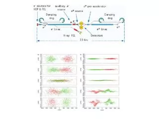
m-Bunching Landau Damped by Laser Heater Ti:saph 758 nm <15 MW Injector at 135 MeV 0.5-m undulator ‘Laser heater’ suggested by Saldin et al., NIMA, 2004; independently by J. Galayda LCLS design study: Z. Huang et al., PRST 2004 (chicane suggested by T. Smith) 14 GeVWith Laser Heater 14 GeV Without Laser Heater Elegant simulations
How does a laser heater work? DgL after chicane after undulator Modulation smeared by half chicane R52 and angular spread lL laser peak power laser rms spot size • The last half chicane time-smears the energy modulation leaving an effective “thermal” energy spread increase
Outline Why a Laser heater? • LCLS setup and measurements • Effects on FEL performance • Anomalous heating effects
Layout of the Laser Heater Optics • Two cameras for monitoring laser beam 758 nm IR laser from laser room • MH2 & MH3 provide laser pointing control • Two OTR screens for spatial alignment • Fast photodiode for timing within ~10 ps transport to the tunnel OTR screens e- MH4 vacuum transport to LH shutter VHC camera wave plate photodiode MH3 MH2 power meter Sasha Gilevich et. al., CH1 camera
Laser Heater Spatial Alignment time energy One button click (~1 minute) IR Calculate and re-align laser poor heating? e- good heating Slide from P. Emma After three iterations, Dave approves it! H. Loos
Laser Heater Temporal Overlap OTR22 BC2 L2-linac • Laser pulse 10-20 ps, electron bunch 5-7 ps • Laser timing done by minimizing the COTR signal after BC2 Laser energy 230 µJ 16 ps COTR signal after BC2 bends (OTR22 inserted) COTR from microbunching suppressed when laser timed Laser delay line in mm (1ps = 0.15 mm)
Heating Measurements YAGS2 YAGS2 YAGS2 RF deflector ON time energy Laser OFF Laser: 230 µJ Laser: 40 µJ σE/E< 12 keV σE/E 120 keV σE/E 45 keV
Slice Energy Spread YAGS2 Double-horn when laser spot ~50% larger than transverse electron beam size More uniform heating when laser spot matches transverse size of electron beam Laser OFF Laser energy 230 µJ σE/E 120 keV
Slice-E Spread vs. Laser Energy Anomalous heating(??) Operating point (~7 uJ) 20 keV compression ratio 75/14GeV = 1.110-4 No heating < 10 keV (limited by resolution)
No Emittance Growth from Heating Laser-induced E-spread in chicane does not introduce emittance growth (< 2%) Heater from 45 mJ to 250 mJ, no change in slice emittance Heater off, COTR after LH chicane biases emittance results 6 ps bunch length
Effects on COTR OTR22 BC2 L2-linac Unwanted microbunching leads to many COTR problems in LCLS • Laser heater suppresses COTR but not to incoherent level OTR22 (heater off) Camera 10 bit depth OTR22 image, heater full Camera 5 bit depth • laser-heated energy profile non-Gaussian • small part of beam escapes heating • Microbunching restart from shot noise after a long linac and some R56 • Alternative diagnostics (wires) used for beam profiles after compressors
Outline Why a Laser heater? • LCLS setup and measurements • Effects on FEL performance • Anomalous heating effects
Laser Heater Improves FEL Power Laser optimal heater OFF 250 pC, 3 kA, 1.5 Å FEL • FEL saturation length • 20 m shorter w/ heater Scan unsaturated FEL w/ 12 undulators vs. heater • FEL saturation power • improves 2X w/ heater
FEL Gain Length vs. Laser Heater Heater OFF 0.01% at 14 GeV with compression factor 90 1.5 Å 0.4-mm emit 0.5-mm emit Heater OFF Heater ON 250 pC, 3 kA, 1.5 Å FEL mbunching effectively increases E-spread to 0.03% ~ 0.04% level
Outline Why a Laser heater? • LCLS setup and measurements • Effects on FEL performance • Anomalous heating effects
“Trickle” Heating Anomalous heating?? Trickle heating peaks at ~ 1 mJ
Laser Modulation Hidden in 4D Phase Space Longitudinal phase space Longitudinal phase space after heater chicane (emittance 0.01 mm) after heater chicane Emittance 0.5 mm Longitudinal phase space x-t correlation x’-t correlation (R52 of half chicane) after undulator after heater chicane after heater chicane • Laser heater at 0.5 mJ (Elegant simulation by Y. Ding)
Modulation Recovered in Real Space x’-t correlation x-t correlation spectr. dipole YAGS2 heater
Longitudinal Space Charge (LSC) x • Consider a beam as shown tilt angle R = Dz/Dx, R is related to transfer matrix • When xR > , longitudinal density modulation is suppressed strongly (exponentially if Gaussian distribution in x) R z In a 1D approach (as used in Elegant), longitudinal modulation multiply by 1D LSC impedance to compute energy modulation modulation amplitude
LSC for Tilted Microbunching • Beam clearly modulated for tilted microbunching in 3D density If beam size sx is much larger than , 3D calculation shows G. Stupakov, private communications D. Ratner, A. Chao, Z. Huang, FEL08 • LSC depends weakly on R when R<1/ • Tilted microbunching does not suppress LSC exponentially. • 1D approach underestimates LSC by a large factor Take L=758 nm, =264, x=60m, R ~2, 1D underestimates LSC by a factor ~250! • Integrating 3D LSC over heater downstream beamline for total energy modulation
Comparison with measurements Trickle heating subtract in quadrature Normal heating LSC induced by laser modulation (theory) LSC + normal laser heating (theory)
Summary • Laser heater is used in the LCLS to improve and optimize x-ray FEL performance at the nominal operating condition. • Microbunching is suppressed but not all COTR is gone alternative diagnostics necessary (wire scanner etc…). • Unexpected “trickle” heating explainable by a 3D LSC model (Preliminary estimation of 1D CSR effect is small, any 3D effect at play?) • Trickle heating does not affect LCLS operation but may have implications to other laser heater designs as well as laser-manipulations of high-brightness beams.
Thanks to: LCLS project director J. Galayda, all commissioning team members, and collaborators and visitors