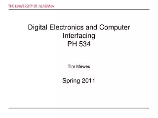
Digital Electronics and Computer Interfacing
Digital Electronics and Computer Interfacing. Tim Mewes 5. Computer Interfacing – DAQ cards. V Supl. +. V 1. V out. V 2. V Supl. -. 5.5 Analog to Digital conversion. 5.5.1 Comparator Device that compares two Voltages and switches its output to indicate which one is larger


Digital Electronics and Computer Interfacing
E N D
Presentation Transcript
Digital Electronics and Computer Interfacing Tim Mewes 5. Computer Interfacing – DAQ cards
VSupl. + V1 Vout V2 VSupl. - 5.5 Analog to Digital conversion 5.5.1 Comparator • Device that compares two Voltagesand switches its output to indicate which one is larger • An OP-Amp can be used as a comparator: Digital Electronics and Computer Interfacing
5.5.2 Direct conversion (flash) ADC Vref=3 V Comparator output HIGH for Vin>Vi R VSupl. - V3 3 2R VSupl.+ VSupl. - V2 2 2R VSupl.+ VSupl. - V1 1 R VSupl.+ Advantage: Speed - conversion typically takes about 10 ns! 0 Vin 5 V Disadvantage: Large number of comparators! Digital Electronics and Computer Interfacing
5.5.2 Successive approximation • Input signal Vin is compared (using a comparator) with a signal VDAC generated by a DAC • Approximate Vin by successively setting the bits of the DAC: • Turn off all bits • Turn on most significant bit if Vin > VDAC leave the bit on otherwise turn it off again • Turn on the next significant bit if Vin > VDAC leave the bit on otherwise turn it off again… • For an n-bit ADC it takes n-steps to converge to the final result • Time for conversion: of the order of s Digital Electronics and Computer Interfacing
5.5.3 Single slope integration • Start ramp generator (constant current source & capacitor) together with a counter that counts clock pulses • When the ramp voltage equals the input Voltage a comparator stops the counter • Number of clock pulses counted is proportional to the input Voltage • Resolution depends on the clock-frequency: the higher the clock-frequency the better the resolution • More bits for the counter needed for higher resolution • Stable clock needed Digital Electronics and Computer Interfacing
Digital Electronics and Computer Interfacing Tim Mewes 6. Computer Interfacing – GPIB bus
6.1 GPIB bus • Digital communication standard for test and measurement devices • Initially developed by Hewlett-Packard (HP), also known as • HP-IB (Hewlett-Packard Instrument Bus) • GPIB (General Purpose Instrumentation Bus) • IEEE-488.x (IEEE Standard Digital Interface for Programmable Instrumentation x:1 or 2) • 8-bit parallel communication • data transfer rates up to 1 Mbyte/s • One System Controller (PC) • up to 15 additional instruments Digital Electronics and Computer Interfacing
6.2 GPIB commands • Over the years three levels of standardizationdeveloped • IEEE 488.1 • IEEE 488.2 • SCPI: Standard Commands for Programmable Instrumentshighest level – devices using SCPI commands are easily to exchangeFor example: all Voltmeters usingSCPI will respond to thesame command Digital Electronics and Computer Interfacing
6.3 GPIB and LabVIEW • GPIB write sends the specified data string to the device referenced by the address string • The address string consists of the primaryand secondary address of the device in the formatprimary+secondary (use MAX to determine those) • Both primary and secondary address can range from 0-30 • Example: for a primary address “0” and secondary address “10” use 0+10 as the address string • The data string depends on the device – use its manual to determine the string for a particular command Digital Electronics and Computer Interfacing
6.3 GPIB and LabVIEW • GPIB read reads byte countnumber of bytes from the devicereferenced by the address string • The command terminates when the specified number ofbytes is read or when a Carriage Return/Line Feed character is received • The data string holds the string received from the instrument – typically this string needs to be processed Digital Electronics and Computer Interfacing
6.3 GPIB and LabVIEW • GPIB queryfirst sends a command and then reads the response of the instrumentquery • Query commands typically end with a question mark: ? Digital Electronics and Computer Interfacing
6.4 GPIB examples • HP 54200 digitizing Oscilloscope Display message: Digital Electronics and Computer Interfacing
6.4 GPIB examples • HP 54200 digitizing Oscilloscope Set the timebase: Digital Electronics and Computer Interfacing
6.4 GPIB examples • HP 54200 digitizing Oscilloscope Set the timebase: Digital Electronics and Computer Interfacing
6.4 GPIB examples • HP 54200 digitizing Oscilloscope Query voltage of a specified point: Digital Electronics and Computer Interfacing
6.5 GPIB using MAX Digital Electronics and Computer Interfacing
6.5 GPIB using MAX Digital Electronics and Computer Interfacing
6.5 GPIB using MAX Digital Electronics and Computer Interfacing