Download
1 / 19
190 likes | 297 Vues
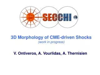
Determination of 3D CME Trajectories using Stereoscopy. Paulett Liewer, Jeff Hall, Eric DeJong, JPL Vahab Pournaghsband, UCB Arnaud Thernisien and Russ Howard, NR L SECCHI Consortium, Orsay, March 2007. Summary. STEREO/SECCHI will provide stereoscopic

E N D
Determination of 3D CME Trajectories using Stereoscopy Paulett Liewer, Jeff Hall, Eric DeJong, JPL Vahab Pournaghsband, UCB Arnaud Thernisien and Russ Howard, NRL SECCHI Consortium, Orsay, March 2007
Summary STEREO/SECCHI will provide stereoscopic images of CME propagation from the Sun to Earth • We use synthetic stereoscopic white light image pairs to test 3D trajectory determination using “triangulation” • Image sequences created from flux rope CME model by A. Thernisien, et al (ApJ 2006) • We obtained good agreement with model parameters for CME velocity, longitude and latitude for 6 blind tests • We address why triangulation works on “features” resulting from LOS integration
CME Model & Synthetic White Light Images A. Thernisien, et al ApJ 2006 • Start with Flux Rope Model CME with density only near surface. CME moves out radially at constant prescribed velocity • Assume a spacecraft separation & calculate time sequence for 3 SECCHI FOVs • Calculate white light images using Thomson scattering Left: view along LOS arrow shown in on right. Black disk is occultor. From Thernisien et al 2006
CME Blind Tests • Thernisien gave us 7 CME cases: • White lights images for COR2, HI1 & HI2 for SC A&B (time sequence of stereo pairs) • SC locations (longitudes, latitude, and distance from Sun) • CME direction and velocity unknown • We used tiepointing, loop tracing and triangulation to track these model CMEs
2008 07 08 17:04:38 UT SC B Earth -x SC A 2008 07 09 10:43:44 UT Sample Synthetic White Light Image SequenceEach frame shows A&B SC + 3 FOVs (Cor2, Hi1, Hi2) (a) (b) A/Hi2 A/Hi1 A/Cor2 B/Cor2 B/Hi1 B/Hi2 2008 07 08 14:33:18 UT (c) (d) y Sim 03 -separation 110°
cor2/B cor2/A 3D Reconstruction of CME Loop • Step 1: User selects ‘seed’ point (X) on the bright CME leading edge in each image of the stereo pair with cursor • tool restricts movement to same latitude sim04_144046_ Repeated for each stereo pair in time sequence Step 2: Routine sunloop traces bright “loop” and uses triangulation on points on the loop to obtain 3D reconstruction of the arcs in the two images
Step 3: View the Results of the 3D Reconstruction • Tool creates a 3D object: the reconstructed leading edge • 3D object can be rotated with cursor/trackball Note: Original model was a 3D flux tube surface whereas our reconstruction is a curve in 3D Here, CME leading edge at two times • Edge coordinates are also written to an ascii file • Files analyzed to find Rmax and its latitude & longitude to track “location” of CME vs time
SC B Earth -x y Tracked and Model Trajectories Radius, Velocity vs Time (model is dashed line) Latitude & Longitude at different times Model X C2 + H1 * H2 SC A Sim 03 again
Summary Results from Six Simulations Very good agreement: <10% error on velocities and < 10º on latitude and longitude for most Why are the results so good? Bright leading edge is a LOS effect!
Why does this work? • Stereoscopy works when tiepoint same feature from 2 viewpoints • CME bright leading edge is not a real feature, but rather a result of LOS integration through a diffuse object
y SC B 60° +20° x -20° SC A COR2 - SC B at +20° COR2 - SC A at -20° Early Test on hemisphere CME for Tiepointing Bright Leading Edge Result: • Leading Edge at 15.1 Rsun vs actual 15 Rsun • Angle of 72° vs actual 60°
Consider Large SC Separations with CME in between SC A y x SC B
Consider Large SC Separations SC A y x SC B
Consider Large SC Separations SC A Increasing Separation Angle • Brings tangent points closer together • LOS “tiepoint” moves closer to true leading edge y x SC B SIMS 1,3,4,5,6 had separation ≥ 90 degrees
A/Hi2 A/Hi1 A/Cor2 y B/Cor2 B/Hi1 B/Hi2 Earth x SC B SC A Lines cross (1) out front of CME and (2) At larger (towards 360 °) longitude as obtained with tracking Sim02 had largest error in LongitudeEach frame shows A&B SC + 3 FOVs (Cor2, Hi1, Hi2) (a) Sim 02- separation 75°, latitude=64° Model longitude 313 ° Tracked longitude 335 ° (b)
y Earth x SC B SC A Sim02: Tracked & Model Trajectories Radius, Velocity vs Time (model is dashed line) Latitude & Longitude at different times Model X C2 + H1 * H2 separation 75° Lines cross (1) out front of CME and (2) At larger longitude, as obtained with tracking
Sim07: New case with 30º separation • We are still analyzing this case • For this much smaller separation angle case, Sunloop automatic loop tracing led to false solution • Reconstructed curve was off by very large angles (50-70°) in both latitude and longitude • Tiepointing WITHOUT use of automatic loop tracing gave good results • More to do!
Conclusions • Can determine CME trajectory (speed, direction) using stereoscopy on white light images for large separation angles • For large angles, errors relatively small - <10% on velocity, a few degrees on direction • Size of error depends on viewing geometry • Now analyzing results for smaller separation angles • Ready to test on STEREO/SECCHI data! • May lead to improved Space Weather prediction