
Advances in ATLAS FP Tracker Design for FE-I4 Sensors at the University of Manchester
E N D
Presentation Transcript
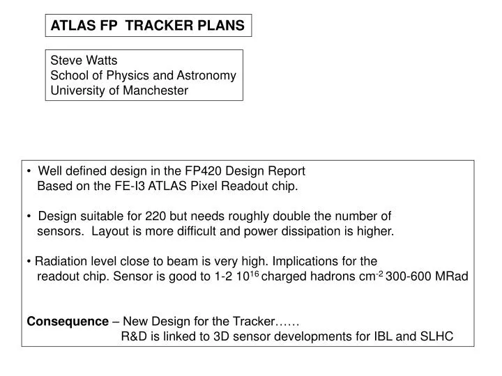
ATLAS FP TRACKER PLANS Steve Watts School of Physics and Astronomy University of Manchester • Well defined design in the FP420 Design Report • Based on the FE-I3 ATLAS Pixel Readout chip. • Design suitable for 220 but needs roughly double the number of • sensors. Layout is more difficult and power dissipation is higher. • Radiation level close to beam is very high. Implications for the • readout chip. Sensor is good to 1-2 1016 charged hadrons cm-2 300-600 MRad • Consequence – New Design for the Tracker…… • R&D is linked to 3D sensor developments for IBL and SLHC
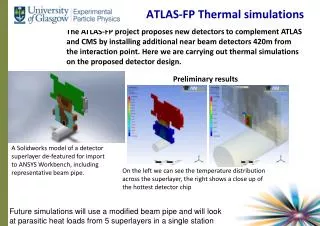
220 m 420 m
FE-I3 Lifetime issue 1015 charged particles per cm2 or ~30 Mrad SOLUTION A 3D sensor safe to 1-2 1016 charged hadrons per cm2 Dose highest in very narrow vertical band. Move sensors up and down by 1-2 mm to even out the dose Trick used with CCDs in NA32. Additional specification for mechanical design. Would give a factor 3.
FE-I3 - lifetime issue Solution B Use FE-I4. Factor 5 more radiation tolerant than FE-I3. For IBL project Plus - better matched to track hit distribution at 220. - Common module design for 220 and 420 - 2 x Fe-I4 each plane 20.2mm ~200μm 7.6mm ~19 mm active IBM reticule 16.8mm 8mm active 2.8mm ~2mm Chartered reticule (24 x 32) FE-I3 74% FE-I4 ~89% • New FE-I4 • Pixel size = 250 x 50 µm2 • Pixels = 80 x 336 • Technology = 0.13µm • Power = 0.5 W/cm2 • FE-I4 Design Status • Contribution from 5 laboratories. • Main blocks MPW submitted in Spring 2008. • Full FE-I4 Review: 2/3/3009 • Submission in Summer 2009 • Expect IBL modules late 2010
NOTE: IMPROVED Y-Measurement. Consequence for physics ??? NOTE2: Assumes hits distribution stable with time…..
FE-I3 versus FE-I4 • FE-I3 run had very poor yield. There will be another run in 2010. • FE-I4 First run will produce chips in summer/Autumn 2010 • ASIC designs always take more than one iteration. • FE-I4 3D sensor is larger and thus yields will be lower. • Conclusion • FE-I4 baseline. There will be 3D/FE-I4 detectors developed for IBL. • Mechanics/electronics engineers to look at FE-I4 design. • FE-I4 - common 220/420 mechanics design