Chapter 3 – Combinational Logic Design
Chapter 3A EGR 270 – Fundamentals of Computer Engineering. 1. Reading Assignment: Chapter 3 in Logic and Computer Design Fundamentals 4 th Edition by Mano . Chapter 3 – Combinational Logic Design

Chapter 3 – Combinational Logic Design
E N D
Presentation Transcript
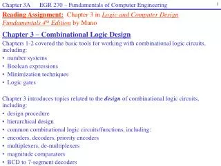
Chapter 3A EGR 270 – Fundamentals of Computer Engineering 1 Reading Assignment:Chapter 3 in Logic and Computer Design Fundamentals 4th Edition by Mano • Chapter 3 – Combinational Logic Design • Chapters 1-2 covered the basic tools for working with combinational logic circuits, including: • number systems • Boolean expressions • Minimization techniques • Logic gates • Chapter 3 introduces topics related to the design of combinational logic circuits, including: • design procedure • hierarchical design • common combinational logic circuits/functions, including: • encoders, decoders, priority encoders • multiplexers, de-multiplexers • magnitude comparators • BCD to 7-segment decoders
Chapter 3A EGR 270 – Fundamentals of Computer Engineering 2 • Types of logic circuits • There are two broad types of logic circuits: • 1) Combinational logic circuits • Circuits whose outputs are determined by logic operations on the input values • Chapters 1-5 deal with combinational logic circuits
Chapter 3A EGR 270 – Fundamentals of Computer Engineering 3 Inputs Combinational Outputs = f(present + past inputs) Logic Memory Sequential Logic Circuit • 2) Sequential logic circuits • Circuits that include memory devices (such as flip-flops) as well as combinational logic so that the outputs are based on both present and past inputs • Sequential logic circuits are introduced in Chapters 6
Chapter 3A EGR 270 – Fundamentals of Computer Engineering 4 • Design Hierarchy • A complex logic system might contain the equivalent of millions of gates. • It would be almost impossible to design a complex system by connecting one logic gate at a time. • A “divide and conquer” approach is used to break the circuit into blocks. • Interconnected blocks form the entire complex circuit. • Large blocks can be broken into smaller blocks. • Each block must have carefully defined functions and interfaces. Key Point: Many logic circuits will be designed with expansion in mind. For example, a 4-bit adder might be designed so that two of them can be combined to form an 8-bit adder.
Chapter 3A EGR 270 – Fundamentals of Computer Engineering 5 Figure 3-2: Design Hierarchy and Reusable Blocks This design approach is referred to as a hierarchical design.
Chapter 3A EGR 270 – Fundamentals of Computer Engineering 6 • Figure 3-3: Hierarchy for Figure 3-2 • The figure below shows the structure of the hierarchy without the interconnections. • Figure 3-3a shows each block and we see that 32 NAND gates are required. • Figure 3-2b is more compact and only shows one copy of each distinct block. • The NAND gates below are pre-defined circuits and are referred to as primitive blocks. • Functional blocks will later be introduced that are predefined reusable blocks providing many basic functions used in digital design. Tool libraries often contain widely used functional blocks.
Chapter 3A EGR 270 – Fundamentals of Computer Engineering 7 • Design Procedure for Combinational Logic Circuits • In Chapters 1-2 we concentrated on analyzing or minimizing given truth tables or logic diagrams. • In Chapter 3 we will concentrate more on designing logic circuits to accomplish a given task. • Chapter 3 introduces a general design procedurethat can be used to design combinational logic circuits. • We will also look at commercially-available logic circuits.
Chapter 3A EGR 270 – Fundamentals of Computer Engineering 8 • Design Procedure (for combinational logic circuits) • Specification: Write a specification for the circuit if one is not provided. • Formulation: Derive the truth table or initial Boolean equations that define the required relationships between inputs and outputs. • Optimization: Apply two-level and multiple-level optimization. Use Boolean algebra, Karnaugh maps, or other techniques to optimize the circuit. • Technology Mapping: Select the technology to be used to implement the design. Options might include: • Implement with AND-OR-NOT gates • Implement with Exclusive-OR gates and other basic logic gates • Implement with only NAND gates or only NOR gates • Implement using decoders • Implement using multiplexers • Implement using PLDs or FPGAs (programmable devices) • Verification: Verify the correctness of the circuit using methods such as: • Hand analysis • PSPICE simulation • VHDL simulation • Build in lab and test the circuit
Chapter 3A EGR 270 – Fundamentals of Computer Engineering 9 Example: Design a 4-bit prime number indicator where the output P = 1 when the binary value of the input ABCD represents a prime number.
Chapter 3A EGR 270 – Fundamentals of Computer Engineering 10 Example: Design a 4-bit magnitude comparator, where the output M = 1 when the inputs A3A2A1A0 and B3B2B1B0 are equal.
Chapter 3A EGR 270 – Fundamentals of Computer Engineering 11 Example: Design a code converter to convert a BCD code to an Excess-3 code. Treat all invalid inputs as don’t cares.
Chapter 3A EGR 270 – Fundamentals of Computer Engineering 12 7-segment displays 7-segment displays are arrangements of 7 LED’s that can be used to display the digits 0-9. 7-segment displays are commonly seen in everyday applications, including consumer electronics, watches, electronic toys, test equipment, and much more.
Chapter 3A EGR 270 – Fundamentals of Computer Engineering 13 Segment designation The 7 segments are lettered a-g in the pattern shown below. The digit 3, for example, can be displayed by turning on segments a, b, c, d, and g. Segments e and f would be turned off. Types of 7-segment displays There are two types of 7-segment displays: 1) common anode (all anodes at +5V) – LOW inputs used to light segments common cathode (all cathodes at ground) – HIGH inputs used to light segments
Chapter 3A EGR 270 – Fundamentals of Computer Engineering 14 BCD-to-7-segment decoder/driver There are two types of BCD-to-7-segment displays drivers: 1) common cathode display driver – This driver must be used with a common-cathode 7-segment display. For each BCD input, it provides HIGH outputs for each segment to be lit (active-HIGH outputs). common anode display driver – This driver must be used with a common-anode 7-segment display. For each BCD input, it provides LOW outputs for each segment to be lit (active-LOW outputs). The 7448 is a commercially available BCD-to-7-segment decoder/driver that is intended to drive a common-cathode display. Note that “current-limiting resistors” are required for each segment. D C B A (LSB) BCD-to-7-segment decoder (with active-HIGH outputs) Common cathode 7-segment display Typical Segment
Chapter 3A EGR 270 – Fundamentals of Computer Engineering 15 Similarly, the 7447 is a commercially available BCD-to-7-segment decoder/driver that is intended to drive a common-anode display. Note that “current-limiting resistors” are required for each segment. D C B A (LSB) BCD-to-7-segment decoder (with active-LOW outputs) Common anode 7-segment display Typical Segment
Chapter 3A EGR 270 – Fundamentals of Computer Engineering 16 • Illustration: If the BCD digit 3 is to be displayed in each case below: • Add binary values to the inputs A, B, C, D • Add binary values to the outputs a, b, c, d, e, f, g Case 1: Common-cathode display D C B A (LSB) Case 2: Common-anode display D C B A (LSB)
Chapter 3A EGR 270 – Fundamentals of Computer Engineering 17 • Unused inputs • Since the BCD-to-7-segment display driver is intended for BCD inputs (0-9), not that inputs some inputs are unused (10-15). These unused inputs could be handled in a variety of ways: • Blank display • Display unique patterns not equal to any of the decimal digits • Treat as don’t cares for simplest circuit. The 7447 and 7448 use this approach. The unique patterns used are shown below.
Chapter 3A EGR 270 – Fundamentals of Computer Engineering 18 Example: Design a BCD-to-7-segment decoder to drive a common anode display with a blank display for all illegal inputs. (K-maps on following slide.)
Chapter 3A EGR 270 – Fundamentals of Computer Engineering 19 CD CD CD CD 00 00 01 01 11 11 10 10 00 00 01 01 11 11 10 10 AB AB AB AB 00 00 00 00 01 01 01 01 CD CD 00 00 01 01 11 11 10 10 11 11 11 11 AB AB 00 00 10 10 10 10 01 01 11 11 10 10 CD 00 01 11 10 AB 00 01 11 10
Chapter 3A EGR 270 – Fundamentals of Computer Engineering 20 • Technology Mapping(Note: The instructor may choose to omit this section) • If an initial design is specified using AND, OR, and NOT gates, the design may then be converted (or mapped) into a new technology. Examples in the text include: • Mapping a design to NAND logic • Mapping a design to NOR logic • Note that NAND and NOR gates are “universal gates”, meaning that they can be used to form any other type of basic logic gates. Figure 3-14 on the following page illustrates the mapping of other gates into NAND and NOR gates. • Show how to form other logic gates using NANDs:
Chapter 3A EGR 270 – Fundamentals of Computer Engineering 21 Figure 3-6: Mapping of AND gates, OR gates, and Inverters to NAND gates, NOR gates, and Inverters.
Chapter 3A EGR 270 – Fundamentals of Computer Engineering 22 • Procedure for converting (mapping) a circuit into NAND or NOR circuits: • Replace each AND and OR gate with the NAND (NOR) gate and inverter equivalent circuits. • Cancel all inverter pairs (back-to-back inverters). • Without changing the logic function, “push” all inverters through branches to represent them as multiple inverters. • Example: Implement the following optimized function with NAND gates and inverters. • F = AB + (AB)’C + (AB)’D’ + E
Chapter 3A EGR 270 – Fundamentals of Computer Engineering 23 Example: Repeat the last example using NOR gates and inverters. F = AB + (AB)’C + (AB)’D’ + E