Electromagnetic waves and Applications Part III:
190 likes | 537 Vues
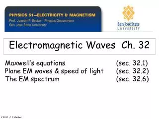
Electromagnetic waves and Applications Part III:. Dr. Yungui MA ( 马云贵 ) E-mail: yungui@zju.edu.cn Office: Room 209, East Building 5, Zijin’gang campus. Microwave Fundamentals. Electromagnetic spectrum. Millimeter waves. Infrared. Radio waves. UV. Microwav es. THz gap. visible.

Electromagnetic waves and Applications Part III:
E N D
Presentation Transcript
Electromagnetic waves and Applications Part III: Dr. Yungui MA (马云贵) E-mail: yungui@zju.edu.cn Office: Room 209, East Building 5, Zijin’gang campus Microwave Fundamentals
Electromagnetic spectrum Millimeter waves Infrared Radio waves UV Microwaves THz gap visible 300 MHz 3 THz 30 THz 300 THz 3 GHz 30 GHz 300 GHz Electronic devices Photonic devices Microwave bands
Microwave applications • Wireless communications (cell phones, WLAN,…) • Global positioning system (GPS) • Computer engineering (bus systems, CPU, …) • Microwave antennas (radar, communication, remote sensing, …) • Other applications (microwave heating, power transfer, imaging, biological effect and safety)
Syllabus • Chapter 1: Transmission line theory • Chapter 2: Transmission lines and waveguides • Chapter 3: Microwave network analysis • Chapter 4: Microwave resonators • Reference books: • David M. Pozar, Microwave Engineering, third edition (Wiley, 2005) • Robert E. Collin, Foundations for microwave engineering, second edition (Wiley, 2007) • J. A. Kong,Electromagnetic theory (EMW, 2000)
Chapter 1: Transmission line theory 1.1 Why from lumped to distributed theory? 1.2 Examples of transmission lines 1.3 Distributed network for a transmission line 1.4 Field analysis of transmission lines 1.5 The terminated lossless transmission line 1.6 Sourced and loaded transmission lines 1.7 Introduction of the Smith chart
Transmission line theory • R = series resistance per unit length, for both conductors, in /m; • L = series inductance per unit length, for both conductors, in H/m; • G = parallel conductance per unit length, in S/m; • C = parallel capacitance per unit length, in F/m. • Loss: R (due to the infinite conductivity) + G (due to the dielectric loss)
Transmission line theory • Bridges the gap between field analysis and basic circuit theory • Extension from lumped to distributed theory • A specialization of Maxwell’s equations • Significant importance in microwave network analysis The key difference between circuit theory and transmission line theory is electrical size. Circuit analysis assumes that the physical dimensions of a network are much smaller than the electrical wavelength, while transmission lines may be a considerable fraction of a wavelength, or many wavelengths, in size. Thus a transmission line is a distributed-parameter network, where voltages and currents can vary in magnitude and phase over its length.
1.2 Examples of transmission lines Electric field (solid lines) (2) Coaxial line (1)Two-wire line Magnetic field (dashed lines) (3) Microstrip line
Review: Kerchhoff’s law 1.3 Distributed network for a transmission line KCL: KVL:
1.3 Distributed network for a transmission line (Telegrapher equations)
1.3 Distributed network for a transmission line Impedance, wavelength and phase velocity TL current: Characteristic impedance: Voltage in the time domain: Wavelength: Phase velocity:
1.3 Distributed network for a transmission line Propagation constant: Characteristic impedance: (what happens if exchange L and C ?) Wavelength: Phase velocity: