Stepper Motor - Parallel Port Interface
Stepper Motor - Parallel Port Interface . By: Jose Rene Flores and Jaime Zavala ECE 345 Project #49. We’ve always been told that all engineering fields are interrelated, but rarely do we get to see this in action.

Stepper Motor - Parallel Port Interface
E N D
Presentation Transcript
Stepper Motor - Parallel Port Interface By: Jose Rene Flores and Jaime Zavala ECE 345 Project #49
We’ve always been told that all engineering fields are interrelated, but rarely do we get to see this in action. Our project aims to incorporate mechanical, electrical, and computer engineering. Introduction
Objective • To design a mechanical device and the logic circuits to control the rotation of a mirror. • Use a stepper motor through a laptop computer’s parallel port interface
Overview Drive circuitry Computer Stepper Motor
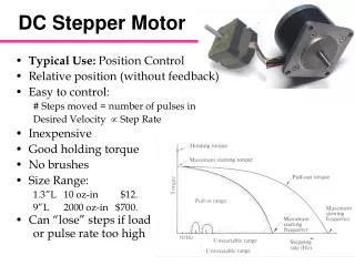
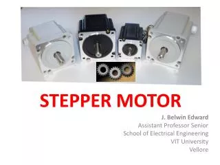
Stepper Motor • Astrosyn mini angle stepper motor • 5V per phase • 1A per phase • 1.8 degrees per step • unipolar type • 200 total poles • available at ECE shop
Drive Circuitry • Resistors cannot draw more than a few milliamps of current • Needed a device that could withstand fast current switching
Drive Circuitry • ULN2003 NPN Darlington transistor arrays • 500mA peak current output • deliver the required current to stepper motor • provide protection against problems associated with inductive loads • well suited for driving lamps, relays, printer hammers, and many industrial applications
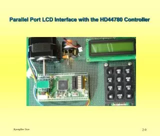
Computer Interface • Motor coils require a sequence of alternating current pulses • Manual operation is too slow • Computer ‘s parallel port is ideally suited for signal transmission • 25 pin male, 36 pin female printer cable
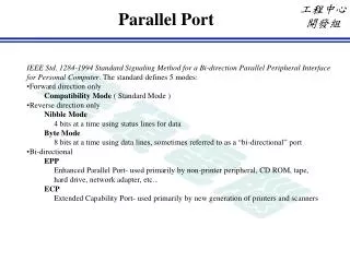
Interfacing the PC • Must know the port’s addresses • needed to write out data with a C program • PC’s have 3 basic types of internal ports • Data - 8 data signals possible (D0-D7) • Status - 5 input signals • Control - 4 signals
Get with the program! • Used C coding for motor control • controls pulse sequence to motor • provides position of motor at all times • gives user the choice of direction to turn • user has choice of degree increments • range from 45 to 180 degrees in 45 degree increments
Testing • Voltage and Current Outputs • Max torque possible from shaft • frequency of operation
Original Design/Concept • Wanted to use a control circuit from ECE 249 • processor and controller • All hardware, no software • Reluctant to attempt a program for control!
Taking the first steps • Generating the required sequences with the 249 circuit using a single input was not possible • Became increasingly clear that a computer program was necessary
Other ideas • ‘Moon shade’ project spinoff • possible use of 5.25 inch disk drive circuitry • Disk drive facilitates using fewer data ports • decide against it, C program easier to implement
Challenges • Apprehensive about programming • How do you work this thing! • darlington array operation
Conclusion • Learned that research is a big part of the design process • Initial designs/concepts probably wont work • Engineering is a continuous learning process