Download
1 / 17
170 likes | 306 Vues
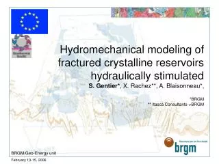
Hydromechanical modeling of fractured crystalline reservoirs hydraulically stimulated S. Gentier* , X. Rachez**, A. Blaisonneau*, *BRGM ** Itasca Consultants->BRGM. BRGM/Geo-Energy unit. (2). (1). (1) Stim. GPK1 -1993 (2) Stim. GPK2 -1995. (3). (4). (3) Injec. GPK2 -1996.

E N D
Hydromechanical modeling of fractured crystalline reservoirs hydraulically stimulatedS. Gentier*, X. Rachez**, A. Blaisonneau*, *BRGM** Itasca Consultants->BRGM BRGM/Geo-Energy unit
(2) (1) (1)Stim. GPK1 -1993 (2)Stim. GPK2 -1995 (3) (4) (3) Injec. GPK2 -1996 (4) Injec. GPK1 -1994 In situ hydraulic stimulation tests at Soultz-sous-Forêts Gérard et al., 1997 • Irreversible increase of the permeability around the wells but not in the same proportions for the all the wells Stimulation curves (GPK1/GPK2) • Micro-seismic events associated to the hydraulic stimulation tests Micro-seismic events (GPK2/GPK3) Engine Gérard et al., 2004
Objectives of our modeling work and of the talk... • Objective of our work at BRGM is: • to understand which physical mechanisms are involved in the hydraulic stimulation of the well in crystalline rocks • to extract the main parameters playing a role in the hydraulic stimulation • to establish the link with the micro-seismic activity observed during the hydraulic stimulation tests • Objective of my talk is much less ambitious : • to give you an idea of the first results obtained up to now by means of some examples extracted from the various hydraulic stimulation tests performed at Soultz-sous-Forêts Engine
6 3 F 2 1 7 5 1000m 400m 400m Hydro-mechanical modeling approach • Conceptual model : • The rock mass is considered as a blocks assembly which are separated by discontinuities • Blocks are deformable and impermeable • Numerical tool : 3DEC code integrating a real HM coupling based on : • Distinct Element method for the mechanical part • Finite difference schema for the hydraulic part of the model in the discontinuities • Aim : to simulate the interaction between mechanical process (deformations, stresses,…) and hydraulic process (pressures, apertures,…) • Flow takes place in the fractures exclusively • Thermal effect is neglected in a first step for two reasons : • we consider very short duration test • we are interested in what it could happen at some distance of the well (the Thermo-Hydro-Mechanical behavior of the near well is in progress with another and more appropriated numerical tool) Engine
well v x=z=0 North sh East Injection under P = Pi + D P sH x = z = 0 x z Pi = r g z y = 0 What kind of data do have we to construct the model ? • hydraulic stimulation tests : solicitation in the well • Stress regime (?): mechanical boundary conditions • Klee and Rummel (1993) • Cornet et al. (to be published) • Fracture network mobilized during the hydraulic stimulation : • identification of this network from : • flow logs • temperature logs • geological analysis (cutting analysis) • bore-hole imagery Engine
V H V h H h What it could happen during the hydraulic stimulation of a well (if we exclude thermal effect...) But in general, the granite is already fractured In continuous homogeneous and isotropic medium Engine
H h Well initial state To Un V opening : reduction of the normal component T1 H Us Increase of the aperture Un release of the shearing Us T2 Tf closure of the fracture More in details... Evolution of the hydraulic aperture is linked to the normal displacement (Un) and the tangential displacement (Us) Engine
Four examples... To illustrate our Hydro-Mechanical modeling approach, we are going to consider the influence of the following parameters : • number of fractures involved in the stimulated network (GPK1) • orientation and dip for a given fracture network (GPK2) • heterogeneity of the hydro-mechanical properties of fractures (GPK3) • stress regime (GPK4) Engine
#8 #1 #1 : the most permeable in situ Model with 8 fractures 6 3 F 2 1 7 5 6 3 3 5 1 4 2 2 1 7 3 5 4 Influence of the number of fractures (GPK1) #1? # 4, 5, 6 Model with 7 fractures No significant change in the global behavior but significant change in the fracture #1 : better fitting with the in situ flow log data Extra fracture (depth 2884 m, dip 80°, dip-dir 230°) connecting two fractures in the upper part of the open hole Hydraulic apertures in the fracture zones Engine
Influence of the number of fractures (GPK1) View in plane of Fracture #1 - Overpressure DP=10.0 MPa Model with 7 fractures Model with 8 fractures Extra fracture GPK1 GPK1 Maximum Aperture # 0.20mm Few meters from well Maximum Aperture = amax = 0.25mm Connection with other fractures Engine
Regular network N 250° -> N 290° Us max 5 cm Us max 2.5 cm Shearing propagates from the top to the bottom of the open hole Shearing is concentrated in the lower part of the open hole Influence of the geometry (GPK2) Tangential displacements P = 14 MPa Statistical network Us max 6 cm Shearing is concentrated in the upper part of the open hole Engine
4750m 4860m 4905m 4930m 4960m 75% of fluid flow 4% of fluid flow 4980m 5015m Heterogeneity of the hydro-mechanical properties (GPK3) Dezayes et al. (2004) Engine
P = 10.5 MPa Influence of the heterogeneity in the hydro-mechanical properties (GPK3) Engine
Slip : points of rupture Micro-seismicity ? Heterogeneity of the hydro-mechanical properties (GPK3) Existence of a very permeable fracture limited extension of shear displacements for this range of overpressures Increase of the permeability remains moderated E W Us max 1 cm Shear displacements 2D/cross section (EW) P = 15 MPa Engine
V ? H h Phyd Stress regime ? 1. Klee and Rummel (1993) H : N170° 2. Cornet et al. (2006?) H : N 175° Normal fault stress regime Strike slip regime Engine
Normal fault stress regime Influence of the stress regime (GPK4) P = 18,3 MPa Tangential displacements more spread Tangential displacements more concentrated in some fractures Strike slip regime Us max 6 cm x 2 Us max 12 cm Engine
Conclusions • Increase of the permeability could be explained by : • shear mechanisms which are developed only in some fracture zones depending of : • geometry and connectivity of the fracture network / stress field • heterogeneity in the hydro-mechanical properties of the fracture in the network This modeling approach can help to understand better a geothermal site but it must be based on a good geological and structural knowledge of the site • Difficulties in relationship with the site : • definition of the in situ stress regime • definition of the fracture network. The model is very sensitive and requires good structural data • how this main stimulated fracture network is connected to the global fracture network constituting the real volume of the exchanger? • Difficulties in relationship with the model : • which law of behavior to consider for the main fracture zone and how to define the associated hydro-mechanical parameters ? Engine