Segment Descriptor
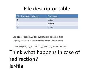
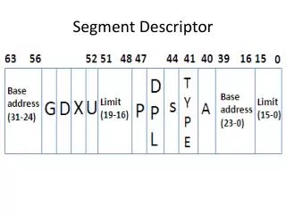
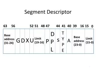
Segment Descriptor. 63. 56. 52. 51. 48. 47. 44. 41. 40. 39. 16. 15. 0. D P L. T Y P E. Base address (31-24). Base address (23-0). s. X. U. G. D. Limit (19-16). Limit (15-0). P. A. . Gate descriptors (S=0, Type 4,5,6,7,C,F).

Segment Descriptor
E N D
Presentation Transcript
Segment Descriptor 63 56 52 51 48 47 44 41 40 39 16 15 0 D P L T Y P E Base address (31-24) Base address (23-0) s X U G D Limit (19-16) Limit (15-0) P A .
Gate descriptors (S=0, Type 4,5,6,7,C,F) • Call gate are used to modified privilege levels. • Trap and interrupt gates are used in interrupt and exception handling. • The task gates are used in multitasking system 31 16 15 8 5 0 Selector Offset (15-0) Word count 4………0 0 0 0 0 Offset(31-16) P DPL Type
Protected Virtual Address Mode Selector offset . Physical address adder Memory operand Segment Base adder Segment descriptor
Segment Descriptor • Segments are areas of memory defined by a programmer and can be a code, data or stack segment. • In 80386 segments need not be all the same size and aligned. And segments need not be exactly 64 KB long, but we can define them to be any length from 1 byte to 4 GB. • In 80386 memory segmentation, it is not possible to use a 16-bit segment register to represent all the information related to segment. When multiple privilege levels and intertask protection are required a special structure called a segment descriptor is used.
Segment Descriptor • The description of a segment includes its base address, length, type, privilege level and some security information. • The lower base address is specified in bits 16 to 39 and upper 8 bits are specified in bits 56 to 63. • The lower 16 bits of segments limit are specified in 0-15 and the remaining 4 bits are specified in 48-51.
Types of segment descriptors segment descriptors System Non-System LDT TSS Gate Stack Data Code
Non System Segment descriptors • Defines data, code, stack segments. • Used by both system and application programs. • S=1 in access right byte.
Non System Segment descriptors • P bit indicates whether segment is present in memory or not. P = 0 -> Segment is not present and P = 1-> Segment is present. • DPL: defines privilege level of the segment. Used to protect segment from low privilege caller.
Non System Segment descriptors • S: Used to distinguish between non system segment and system segment descriptors. • S = 1-> Non system segment descriptor. • E: Executable; Used to distinguish between data and code segments. E=0 -> Data segment including stack. E = 1 -> Code segment. • ED/C: Expand direction/conforming; When E=0, then this bit functions as ED, ED indicates whether the segment is data or stack. ED = 0 -> Data segment( access segment randomly). Offset address limit. ED = 1 -> Stack segment LIFO.
Non System Segment descriptors • When E =1, then this bit functions as C ( conforming) bit. Used to distinguish between conforming and nonconforming code segments. • C= 0 -> Non conforming code segment. • C = 1 -> Conforming code segment. • R/W Read/Write. When E= 0( data segment), then this bit functions as W bit. This bit indicates whether data segment is writable or not. • W = 0 -> data segment is not writable. W= 1 -> data segment is writable.
Non System Segment descriptors • When E =1 (code segment) then this bit functions as R bit. This bit indicates whether code segment is readable or not. R = 0 -> code segment is not readable and R = 1 -> code segment is readable. • A: Accessed; This bit indicates whether the segment is accessed or not. A= 1 -> Segment accessed. This bit is reset by OS periodically. A= 0 -> Segment not accessed
System Segment descriptor Type • All system descriptors are present in GDT while some system descriptors are present in LDTs. • Normally system segment descriptor are used by OS. • The value of S in right access byte is 0. • Their functions are fixed and specified by Intel. • The type of system descriptor is indicated by type field. • The system segment descriptors have no Accessed bit, instead the type field (3 bits) is now extended to 4 bits. • The system segment descriptors contain the information about tables (LDT), tasks(TSS) and gates (call gate, interrupt gate, task gate, trap gate) of the OS.
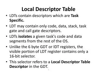
LDT descriptor (s=0, Type 2) • The LDT descriptors are present in the GDT. They contain the information about the LDT. • LDT contains the segment descriptors that are unique to a particular task. • The DPL field of the descriptor is ignored as this descriptor can only be accessed with a privilege level of 0. • Here type field =2 i.e. it specifies a LDT descriptor.
TSS (Task State Segment) Descriptors (s=0, Type 1, 3, 9 and B) • Whenever a computer is performing more than one tasks at a time it may also switch between these tasks. • The task may be a single program or a group of program. • When one task switches to another task , it stores all the necessary information required to restart the task where it was left. This information is called as the “ state of the task” • For storing the state of the task the 80386 processor uses a special segment called the “Task State Segment (TSS)”
TSS (Task State Segment) Descriptors (s=0, Type 1, 3, 9 and B) • The task segment is addressed with the help of TSS descriptor. It contains information about the location, size and privilege level of a TSS. • A TSS descriptor appears only in GDT and not in IDT or LDT. • The TSS consists the linkage field for the nest task that permits the nesting of the tasks.
TSS (Task State Segment) Descriptors (s=0, Type 1, 3, 9 and B) • B bit indicates whether task is busy or not. B=0 : Task is not busy B=1 : Task is busy
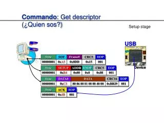
Gate descriptors (S=0, Type 4,5,6,7,C,F) • Whenever 4,5,6,7 is specified in type field it specifies a call gate, task gate, interrupt gate and trap gate respectively. • All fields are same as specified earlier except the word count, selector and offect. • The word count field specifies the number of parameters that are to be copied from caller’s stack to the called procedure’s stack.
Gate descriptors (S=0, Type 4,5,6,7,C,F) • Call gate are used to modified privilege levels. • Trap and interrupt gates are used in interrupt and exception handling. • The task gates are used in multitasking system
Protected Virtual Address Mode Physical address calculation in the protected virtual address mode
Protected Virtual Address Mode 1) PLs > Pldesc->access to segment allowed. 2)MMU checks__> Pdesc determine__> segpresent__>phymem. 3) exception load__>segmemreturn__> interrupted prog. 4) 1st & 2nd step satisfied MMU will add 16 bit offset.
Descriptor tables • The segment descriptors are grouped together and placed in a continuous memory location and this group arrangement is known as descriptor tables . • It contain 8192 descriptors and max length is 64KB. Each descriptor requires 8 bytes in order to store the data of particular segment. • There are 3 types of descriptor tables. • 1)GDT 2) LDT 3) IDT
Global Descriptor Table Registor (GDTR) and GDT • 48 bit register. • Used to point GDT. • Divided into two components viz. Base and limit. • Base value( 32 bit) indicates the starting address of GDT. • Limit value(16 bit) indicates the size of GDT. • Used by OS only(GDTR). • Initialized in real mode. • Defines characteristics of global address space. • It has no cache register.
Global Descriptor Table Registor (GDTR) and GDT • GDT can be used by all programmers to refer to the segment of memory. • 80386 processor in protected mode can have many LDT’s but only one GDT. • It may contain special system descriptors.
LIMIT -> 16 bit field. Indicates the length of GDT in terms of bytes. The maximum size of GDT is 65536 bytes.Limit = Size -1e.g. if LIMIT = 00 F F Hthen size of GDT = 256 bytesBASE -> 32 bit field. Gives 32 bit physical starting address of GDT. 16 15 0 BASE LIMIT 47
LDTR and LDT • 16 bit register. • Used as a local selector. • Points LDT descriptor stored in GDT. • GDT contains many LDT descriptors. • E ach LDT has LDT descriptor in GDT. • Points only one LDT descriptor at a time. • Used to change LDT. • Provides 48 bit cache register. • A 48 bit cache register is used to hold current LDT descriptor. • E ach task may have it’s own LDT and can also be shared with other tasks.
LDTR • Lower 3 bits are always zeros. Upper 13 bits are used as Index Value • Index value is multiplied by 8 and added into base address stored in GDTR. • Physical Address of LDT descriptor in GDT = Base address in GDTR + (Index value8). 15 3 2 0 13 bit Index Value 0 0 0
LDTR CACH E R E GIST E R • This Register is not available for user. • It holds LDT descriptor of current LDT. • Base address is the physical address of LDT. • Limit indicates the size of LDT. Limit = Size -1 • Access right provides protection mechanism. 32 BIT BASE Address of LDT 16 BIT LIMIT Access Right
Local Descriptor Table • Local Descriptor Table • E ach task can have access to own private descriptor table(LDT) in addition to GDT. • Contains descriptors that provide access to code and data in segments of memory. · · · 15 0 GDT GDTR LIMIT 31 BASE 15 0 LDTR · · · selector LDT0 LDTR cache 0 15 LIMIT 31 BASE program invisible · · · LDTn
LDTR • The LDT is also called as “private table” which defines a local memory address space for use by the task. • E ach task can have its own segment of local memory. So there may be many LDT’s in protected mode, say LDT-0 to LDT-n. • for loading the value in the GDTR, LDTR, IDTR the 80386 provides the instructions LGDT, LLDT, LIDT. Similarly for storing we have SGDT, SLDT and SIDT
Interrupt Descriptor Table • Interrupt Descriptor Table (IDT) • Contains interrupt descriptors, not segment descriptors. • IDT can also be up to 64KB; But 386 only supports up to 256 interrupts and exceptions(2KB). 255 Interrupt Descriptor Table (IDT) Interrupt Descriptor Table Register(IDTR) MAX: 2k bytes 256 entries 16 15 47 0 LIMIT BASE 1 0
IDTR • 48 bit register. • Points IDT. • IDT contains descriptors. Maximum 256. • Consists of base and limit value. • Base address indicates the starting address of IDT. • Limit value indicates the size of IDT. • Used by interrupts and exceptions only. • ISRs are invoked via IDT. • It has no cache register. • The descriptors used in the IDT are called as “interrupt gates” which gives the beginning of an interrupt-service routine(ISR).
IDTR • Base address is the physical address of IDT. • Limit value indicates the size of IDT. • Limit = Size –1. • The maximum size of IDT is 256 8.. 15 47 16 0 32 bit Base address of IDT Limit 16 bit Not more than 256*8-1
Logical to physical address translation . SELECTOR OFFSET LOGICAL ADDRESS SEGMENT TRANSLATION PG? PAGING DISABLED PAGING ENABLED 0 31 DIR PAGE OFFSET LINEAR ADDRESS PAGE TRANSLATION PHYSICAL ADDRESS
Memory management • Three components: logical, linear and physical • Transfers logical address into physical address in two steps viz. segment and Page translation • Logical address consists of segment selector and segment offset. This address is converted into a linear address. Logical address is also called virtual address. • Segmentation is a process of converting logical address to a linear address. It provide memory management as well as protection. • In page translation, the linear address is converted into physical address (optional). • Segment provides a mechanism of isolating individual code, data and stack modules so that tasks can run on the same processor without interfering with one another. • Paging provides a mechanism of implementing a conventional demand-paged, virtual memory system. Provides isolation between tasks.
Segment & page Translation Process • In order to generate the 32 bit linear address, the base address from the descriptor is added to the 32 bit offset. This process is called as segment translation. • If the paging mechanism is not enabled then the 32 bit linear address is the physical address. But if the paging mechanism is enable then the linear address is transform to physical address. This process is called paging translation. Thus, the logical address is converted to physical address.
Memory management • Segmentation unit translates the logical address into 32 bit linear address. • Paging unit converts 32 bit linear address into 32 bit physical address. • Paging mechanism manages only one segment at a time. • Paging mechanism manages huge segment. • Semiconductor memory contains segments and descriptor tables.
P aging: Address Translation • It is the second phase of address translation. Here 386 processor converts the linear address that is generated by the segment address translation to physical address. • This step is optional. It is mandatory only when the OS has to implement 1)multiple virtual 8086 tasks 2)page oriented protection 3) page oriented virtual memory. • P G =1, physical address space(4GB) consists of 1,048,496 pages. Each page is of 4096 byte (4KB) long. • The creation of unused section of memory is called as “fragmentation”. In paging process, the fixed size of the page gives fragmentation.