Download
1 / 12
280 likes | 1.03k Vues
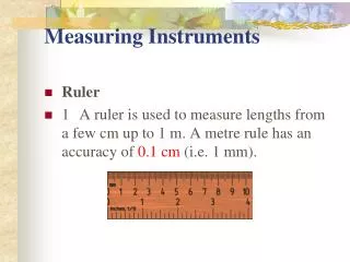
Tools and Electrical Measuring Instruments. Topic: Reading engineering drawings. Incomplete – add 5 questions and video and image briefs. Assumed prior learning. Outcomes. On completion of this unit, you will be able to read and interpret an engineering drawing.

E N D
Tools and Electrical Measuring Instruments Topic: Reading engineering drawings Incomplete – add 5 questions and video and image briefs
Outcomes On completion of this unit, you will be able to read and interpret an engineering drawing.
Introduction Now you know what the abbreviations and symbol on this drawing mean. You are one step closer to helping Katlego know what he needs to buy to put this equipment together. Can you see what these measurements are indicating? Why do you think we use mm and not m or cm? Repeat intro image from Unit 1 Click here to enlarge the image and look at the measurements on the drawing.
Dimensions Have you noticed that drawings are usually dimensioned in millimetres? When we need a high degree of accuracy, dimensions are given in decimal parts of a millimetre. This will ensure greater precision. Click here to see why Katlego still needs your help. SME: Please assist with this video. What can demonstrate the info described below?
SME: Please assist with this slide Tolerances Now you have seen that even if we know the dimensions of an object, sometimes we need to see that allowances are made for parts to be oversize or undersize. These are called tolerances. The plus symbol + means that the machined surface can be larger, and - minus means that it can be smaller than the dimension stated on the drawing. This image shows it can be 1/100 mm or 0,01 mm larger or smaller, i.e. it can be any size between 49,99 mm to 50,01 mm.
Tolerances What can you tell about the tolerances shown on this diagram? • The size can be larger by 0,01mm but not smaller than the dimension given. • The size can be between 49,99mm and 50,01mm. • The size can be smaller than the given dimension but not larger.
At last… You should be able to interpret engineering drawings now. Describe what you would tell Katlego to buy so that he can assemble the equipment he needs. [Space to type in – for ePortfolio?] Repeat intro image from Unit 1 Click here to see if you were correct.
A Quick Quiz Before we end off, take some time to check your understanding of what we have covered in this unit by answering the following questions. Incomplete – add 5 questions