Download

1 / 33
330 likes | 560 Vues
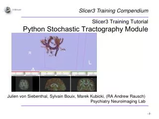
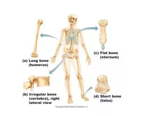
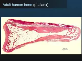
Slicer3 Training Compendium. Slicer3 Training Tutorial IA-FEMesh v1.0 Proximal Phalanx Bone. MIMX Laboratory Center for Computer Aided Design Engineering Research Facility The University of Iowa Iowa City, IA. Learning Objectives. Following this tutorial, you’ll be able to:

E N D
Slicer3 Training Compendium Slicer3 Training Tutorial IA-FEMesh v1.0 Proximal Phalanx Bone MIMX Laboratory Center for Computer Aided Design Engineering Research Facility The University of Iowa Iowa City, IA
Learning Objectives • Following this tutorial, you’ll be able to: • find the IA-FEMesh module in Slicer3 • generate a mesh representation of the proximal phalanx bone of the human hand • apply IA-FEMesh to your own application
Prerequisites This tutorial assumes that you have already completed the tutorial Data Loading and Visualization. Tutorials for Slicer3 are available at the following location: • Slicer3 tutorialshttp://www.na-mic.org/Wiki/index.php/Slicer3.2:Training
Materials This tutorial requires the installation of the Slicer3 software and the tutorial dataset. They are available at the following locations: • Slicer3 download page (Slicer 3.4) http://www.slicer.org/pages/Downloads/ • Tutorial dataset (MeshTutorialExampleData.zip) http://www.na-mic.org/Wiki/images/5/5a/MeshTutorialExampleData.zip Disclaimer:It is the responsibility of the user of Slicer to comply with both the terms of the license and with the applicable laws, regulations, and rules.
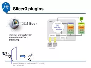
Overview • Part A: Introduction to the IA-FEMesh module • Part B: Mesh the proximal phalanx bone
Locating IA-FEMesh Open Slicer3 Locate the “Modules” drop down menu Select IA-FEMesh in the “Modules” drop down menu 2. 1.
Loading Image Files Select the Image Tab Select Load on drop down menu Select the image file to load Uncheck the checkbox in the Object Manager to temporarily hide the loaded image 1. 2.
Loading Surface Files Select the Surface Tab Select Load on drop down menu Select the surface file to load 1. 2.
Creating a Building Block Select the Block(s) Tab Select Create from the drop down menu Check Create Block from Surface Bounds Click Apply 1. Sample Generated Building Block 2. 3. 4.
Manipulating the Building Block • Select the Blocks tab • Select Build/Edit from the drop down menu • Select the from the building blocks toolbar • Allows manipulation of vertices, edges, and faces of building blocks • Red spheres will appear at the vertices. The size of these spheres can be scaled 1. 3a. 2. 3b.
Manipulating the Building Block(2) • To move a vertex or face, simply click the left mouse button and drag it to the desired position • To move an edge, click the middle mouse button and drag it to the desired position • Click Cancel to exit building block manipulation • To save the building block, select Save from the drop down menu • Note: • Active elements turn green • Inactive elements remain red
Assigning Mesh Seeds to the Building Block Select the Mesh tab Select Assign/Edit Mesh Seeds from the drop down menu 1. 2.
Assigning Mesh Seeds to the Building Block(2) • Select the button to visualize the distribution of mesh seeds • To change this assignment, select either Element Length or Number of Divisions from the drop down menu. • Click on a block with the left mouse button • Enter the values of your choice • Select Apply • Select Cancel to exit the mesh seeds operation 3. 5. 4. 6. 7. 8.
Creating a Mesh 1. Select the Mesh tab Select Create from the drop down menu Select Volumetric Mesh Select Building Block in the following drop down menu Provide starting node/element numbers and a descriptive label to be associated with the mesh definition Selection Elliptical in the Interpolation drop down menu Uncheck Perform Smooth for the initial attempt Select Apply to generate the mesh 2. 3. 4. 5. 6. 7.
Checking Mesh Quality Select the Quality tab Select Evaluate/Display MeshQuality from the drop down menu 1. 2.
Checking Mesh Quality (2) • Select your Metric of Choice from the Metric drop down menu • Click the button • Close summary report window after viewing • Click Cancel to exit the mesh quality check module 3. 4.
Improving Mesh Quality Select the Quality tab Select Mesh Improvement from the drop down menu Check to ensure that the surface, block, and mesh of interest populate the Mesh Component frame Select an interpolation method from the Interpolation drop down menu Enter the desired number of smoothing iterations for the external nodes Click Apply 1. 2. 3. 4. 5. 6.
Improving Mesh Quality(2) • Adjust the smoothing parameters by toggling between the Evaluate/Display Mesh Quality and Mesh Improvement operations until the desired mesh is achieved • While displaying the metric of interest in the Evaluate/Display Mesh Quality module, press the button to invoke a cutting plane to view the internal elements.
Assigning Material Properties – User Defined • Select the Materials tab • Select the User-Defined option from the main menu • To add additional element sets, press • A number of options are available for selecting element sets
Assigning Material Properties – User Defined(2) • Element Set Definition Examples • Cortical Bone Set Definition • Hold Ctrl button while using the left mouse button to drag a rubberband box around the elements of interest • Selected elements will be green • To accept the chosen elements, click the right mouse button while hovering over the mesh • Accepted elements will turn red • Opacity can be modified to better visualize the data • Once the selection is finalized, enter a Set Label (e.g. cortical bone) • Click to accept the selection • Cancellous Bone Definition • Repeat the steps above except hit the button prior to accepting the element selection and assigning a new Set Label. • Reduce the opacity to see the element set you have defined • Click the button to close the Define Element Set window 1. 2.
Assigning Material Properties – User Defined(3) • Material Property Assignments • Select an element set using the “Element Set” drop down menu • Enter the desired Modulus • Enter the desired Poissson’s Ratio • Click Apply • Repeat this procedure for each material assignment • Click Cancel to exit the operation 1. 2. 3. 4. 6.
Assigning Material Properties – User Defined(4) • Visualizing the Material Property Assignments • Select the Materials tab • Select Display Material Properties from the drop down menu • Select the desired element set from the Element Set drop down menu • Use the button to display a cutting plane which may be manipulated to view internal element definitions 2. 3. 4.
Assigning Material Properties – Image Based • At this point, you can overwrite your user-defined properties, or skip this step entirely • Select the Materials tab • Select the Image-Based option from the main menu • Expand the “Mesh & Image Assignments” frame • Ensure that the appropriate Mesh and image definitions are present 1. 2.
Assigning Material Properties – Image Based (2) • 5. For each element set previously defined: • Select the element set of interest • Assign a Poisson’s Ratio by selecting the button and adjust the constants for the modulus calculation • Select a method of calculating density for a given element • Select Apply in the Image-Based Elastic Modulus window • Select Apply in the Materials Panel to commit the image-based properties to the mesh • Repeat this procedure for all element sets that were previously defined 5a. 5b. 5b. 5c. 5d.
Assigning Load and Boundary Conditions • Select the Load/BC tab • Select the STEP – Load/BC Assignments from the drop down menu • Select • Select from the Node Set toolbar • This enables the nodes associated with a face of a building block to be readily chosen 4. 1. 2.
Assigning Load and Boundary Conditions (2) • Hold the Ctrl button and use the left mouse button to choose a node associated with the building block face of interest • Nodes associated with selected face will be highlighted in green • To accept the chosen nodes, click the right mouse button while hovering over the mesh • All nodes associated with the chosen face will turn red • Opacity can be changed using the slider bar • Once the selection is finalized, enter a Set Label • Click • Click 6. 7. 8. 9.
Assigning Load and Boundary Conditions (4) • Provide a descriptive heading in the Step Subheading textbox • Select desired Load/Displacement typein the drop down menu • Select the appropriate Node Set • Assign x, y, and z directions 11. 12. 13.
Assigning Load and Boundary Conditions (5) • Select Apply to update the Load/BC assignments • Visual confirmation will be provided on the mesh in the View Panel 15.
Assigning *STEP Definitions • Select the *STEP Definitions button • Please refer to the ABAQUS manual regarding these parameters • Use the NSET and ELSET drop down menus to select the sets of interest • Click Apply in each submenu to commit your selection
Final Steps • Save the FE Mesh • Select Save from the Mesh Tab • This can be performed at any step through the mesh development process • Export the FE Mesh in ABAQUS file format • Select Export ABAQUS file from the Mesh Tab • This can be performed at any step through the mesh development process
Acknowledgements National Alliance for Medical Image Computing NIH U54EB005149 National Institute of Biomedical Imaging and Bioengineering R21EB001501 and R01EB005973 Musculoskeletal Imaging, Modeling, and EXperimentation (MIMX) Program, The University of Iowa