Viewing
Viewing. How to see the object Type of object view How to set the view for CG The shadow creating. Type of Views Examine how an app viewer can create a particular view within OpenGL Use model-view matrix to switch from world frame to camera frame: camera at origin


Viewing
E N D
Presentation Transcript
Viewing How to see the object Type of object view How to set the view for CG The shadow creating suriyong l.
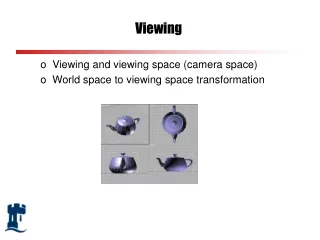
Type of Views • Examine how an app viewer can create a particular view within OpenGL • Use model-view matrix to switch from world frame to camera frame: camera at origin • Preferred projection type : • parallel, perspective suriyong l.
OpenGL® Geometry Pipeline MODELVIEW matrix PROJECTION matrix perspective division viewport transformation original vertex final window coordinates normalized device coordinates (foreshortened) 2d projection of vertex onto viewing plane vertex in the eye coordinate space
Viewing Principle of view • Classical view and computer view are Similar COP at infinity COP: Center Of Projectionex. eye , camera lens, for CG: the camera frame DOP: Direct OP - view at infinite distance suriyong l.
COP condition • Finite distance view • perspective view • Infinite distance view • Parallel view • Limiting case of perspective view • Treat as separate case • API support both view • User easily switch between view • Use planar geometric projection viewing method: • Object project on planar surface (plane and projection lines) • 2 types of view for CG but classical permit more than one viewer one-, two- etc. suriyong l.
3D 2D Projection • Type of projection depends on a number of factors: • location and orientation of the viewing plane (viewport) • direction of projection (described by a vector) • projection type: Projection Perspective Parallel 1-point Orthographic 2-point Axonometric 3-point Oblique
Classical views Classical view • Underlying notion of principal face • Object is composed of a number of planar faces front, back, top, bottom, etc. suriyong l.
Orthographic projection Temple and three multiview orthographic projections Orthographic projections • An Orthogonal view • Projectors are perpendicular to projection plane • Multiview Orthographic projection • Projection plane is parallel to one of the principle faces, usually 3 faces suriyong l.
Orthographic properties • Preserve both distances and angles: • No distortion in shape • Projectors perpendicular to plane • Projection plane is parallel to one principal of object face • Applied in drawings suriyong l.
Axonometric projection • Plane rotational orthogonal projection • Plane is not perpendicular to 1 face • Special case • Isometric : • plane is places symmetrically with 3 simple faces • Dimetric: • plane is places symmetrically with 2 simple faces • Trimetric • No faces are places symmetrically with plane suriyong l.
Axonometric projections. (a) Construction of trimetric-view projection. (b) Top view. (c) Side view. Axonometric views suriyong l.
Viewing System • We are only concerned with the geometry of viewing at this stage. • The camera’s position and orientation define a view-volume or view-frustrum. • objects completely or partially within this volume are potentially visible on the viewport. • objects fully outside this volume cannot be seen clipped view frustrum clipping planes clipped
Camera Models • Each vertex in our model must be projected onto the 2D camera viewport plane in order to be display on the screen. • The CTM is employed to determine the location of each vertex in the camera coordinate system: • We then employ a projection matrix defined by GL_PROJECTION to map this to a 2D viewport coordinate. • Finally, this 2D coordinate is mapped to device coordinates using the viewport definition (given by glViewport()).
Camera Modeling in OpenGL ® camera coordinate system viewport coordinate system device/screen coordinate system glViewport(0,0,xres,yres) glMatrixMode(GL_MODELVIEW) ... glMatrixMode(GL_PROJECTION) ...
Parallel Projections orthographic axonometric oblique
Perspective Projections 3-point perspective 1-point perspective 2-point perspective
Orthogonal Projections • The simplest of all projections, parallel project onto view-plane. • Usually view-plane is axis aligned (often at z=0)
Multiple Projections • It is often useful to have multiple projections available at any given time • usually: plan (top) view, front & left or right elevation (side) view Perspective Top Front Right
Orthogonal Projections • The result is an orthographic projection if the object is axis aligned, otherwise it is an axonometric projection. • If the projection plane intersects the principle axes at the same distance from the origin the projection is isometric.
Parallel Projections in OpenGL® glOrtho(xmin, xmax, ymin, ymax, zmin, zmax); Note: we always view in -z direction need to transform world in order to view in other arbitrary directions.
Perspective Projections • Perspective projections are more complex and exhibit fore-shortening (parallel appear to converge at points). • Parameters: • centre of projection (COP) • field of view (q, f) • projection direction • up direction
Oblique view (a) Construction. (b) Top view. (c) Side view. Oblique View • Projector make an arbitrary to projecting plane • Able to see more than 1 face at the same time • Most difficult to draw by hand • Lens parallel to plane • Unnatural suriyong l.
Classical perspective views: The (a) three-, (b) two-, and (c) one-point perspectives Perspective view Perspective View • Diminution of size • Unable to measure • Real-lookingimage • For classical perspective 1-, 2- or 3- point perspective suriyong l.
The Camera System • To create a view of a scene we need: • a description of the scene geometry • a camera or view definition • Default OpenGL camera is located at the origin looking down the -z axis. • The camera definition allows projection of the 3D scene geometry onto a 2D surface for display. • This projection can take a number of forms: • orthographic (parallel lines preserved) • perspective (foreshortening): 1-point, 2-point or 3-point • skewed orthographic
Camera Types • Before generating an image we must choose our viewer: • The pinhole camera model is most widely used: • infinite depth of field (everything is in focus) • Advanced rendering systems model the camera • double gauss lens as used in many professional cameras • model depth of field and non-linear optics (including lens flare) • Photorealistic rendering systems often employ a physical model of the eye for rendering images • model the eyes response to varying brightness and colour levels • model the internal optics of the eye itself (diffraction by lens fibres etc.)
Modeling the Eye’s Response Adaptation Glare & Diffraction
Camera Systems A camera model implemented in Princeton University (1995)
Initial camera position. Computer view principle • OpenGL View • Perspective camera – 1 point of view • Orthogonal camera suriyong l. Imaging using the default camera.
Movement of the camera and world frames. (a) Initial configuration. (b) Configuration after change in the model view matrix Initial camera position. Positioning of the camera • Convert reference of model frame to camera frame • First at point P (both frame at vertex) • Last at point Q • Camera frame C suriyong l.
Suppose to see object at +x direction glMatrixMode(GL_MODELVIEW); //Initialize matrix_mode to Model_view glLoadIdentity(); glRotatef(90.0, 0.0, 1.0, 0.0); // move camera to x axis (rotate around +y)glTranslatef(0, 0, -d); // Translate far from origin with distance d suriyong l.
Create Isometric view • Object moving • Transform object to isometric view type • Camera moving • Move the camera to the isometric view type suriyong l.
Object moving // Assume that we have 2 unit cube glMatrixMode(GL_MODELVIEW); glLoadIdentity(); glTranslatef(0.0, 0.0, -d); // move camera backward glRotatef(35.26, 1.0, 0.0, 0.0); // Rotate around x axis (35.26o) // Point (-1, 1, 1) move to (0,0, √2) glRotatef(45.0, 0.0, 1.0, 0.0); // Rotate around y axis (45o) glOrtho(…); // view clipping The (-1, 1, 1) is rotate to the new point (0, 0, √2) and translate to -d suriyong l. positive z-axis view x-axis view
Create an Isometric view • Symmetrically rotate object to see 3 faces together • Rotate about the y-axis (45o) and x-axis (-35.26o) consequently • Move away from WCS with distance d M = T(-dz).Ry(45) .Rx(-35.26) suriyong l.
Camera moving Two Viewing APIs (Normalization transformation process) Camera frame. Start at world frame, camera at origin look to –z direction, define the projection point on projection plane as VRP (View Reference Point) Specify VRP – View Reference Point with user’s function set_view_reference_point(x, y, z); Specify camera orientation: fix the camera orientation - user’s function VPN (View Plane Normal vector - n) set_view_plane_normal(nx, ny, nz); VUP (View UP vector) : up direction set_view_up(vup_x, vup_y, vup_z); suriyong l.
Let p is VRP View plane normal (n) Determination of the view-up vector. Specify vfromVUP Projection Create ufrom v, ncross product Get new orthogonal coordinate systemu-v-ncalledviewing-coordinate system matrix that does change frame called view-orientation matrix VUP Target: Fine the isometric matrix which composed of translation and rotation V = RT// V: the isometric matrix Steps: Move the camera to the VRP by translation matrix let T (-x, -y, -z) suriyong l.
suriyong l. Handing rotation Find as factor of and Let (don’t care the length of at first) and is the proportion of and Find from and : Modify vectors to their normalize form Let are normalized form of Create rotation matrix M from
suriyong l. We need matrix in the form of inverse thus, R = M-1 = MT ; R is the rotation matrix Finally, multiply by T then Note: Translation matrix is on the right: Object moves to the left, Camera moves to the right. Camera was specified in the world frame both have similar forms
Look-at positioning. The Look-At function • Isometric viewing function • Use model of VRP, VPN and VUP gluLookat(eyex, eyey, eyez, atx, aty, atz, upx, upy, upz); eyex, eyey, eyez : location of VRP atx,aty, atz : target object (VPN = [atx-eyex, aty – eyey]) upx, upy, upz : (VUP = [upx-eyex, upy-eyey]) suriyong l.
OpenGL application sequence void display() { glMatrixMode(GL_MODELVIEW); glLoadIdentity(); gluLookAt(eyex,eyey,eyez, atx,aty,atz, upx,upy,upz); . . . // define objects here } suriyong l.
Positioning the Camera • The previous projections had limitations: • usually fixed origin and fixed projection direction • To obtain arbitrary camera orientations and positions we manipulate the MODELVIEW matrix prior to creation of the models. This positions the camera w.r.t. the model. • Ex. position the camera at (10, 2, 10) w.r.t. the world • Two possibilities: • transform the world prior to creation of objects using translatef androtatef:glTranslatef(-10, -2, -10); • use gluLookAt to position the camera with respect to the world co-ordinate system: gluLookAt(10, 2, 10, … ); • Both are equivalent.
Positioning the Camera gluLookAt(eyex, eyey, eyez, lookx, looky, lookz, upx, upy, upz); θ ϕ equivalent to: glTranslatef(-eyex, -eyey, -eyez); glRotatef(theta, 1.0, 0.0, 0.0); glRotatef(phi, 0.0, 1.0, 0.0);
Roll, pitch and yaw Elevation and azimuth Other Viewing APIs suriyong l.
Perspective Projection Condition: COP at the origin Camera point to –ve Z axis We will consider the first case in detail Two possibility of camera for perspective projection (a) view plane parallel to lens and normal to z axis (b) view plane not parallel, but lens orthogonal to z axis suriyong l.
Three views of perspective projection. (a) Three-dimensional view. (b) Top view. (c) Side view. • Calculation step • Let point in space is located at • Projection plane is perpendicular to –z axis and located at z = d • Project that point to projection plane, let’s say • Summary • Non uniform shortening • The farer of object, the size is much more reduce suriyong l.
Projection pipeline. Using homogeneous coordinate Thus Perspective projection transformation If divided by 4th component suriyong l.
Orthogonal projection Orthogonal Projection • Special case of perspective projection • Projectors are perpendicular to view plane • Rather than cop at infinity, let z = 0 then Transformation matrix form suriyong l.
Definition of a view volume Front and back clipping planes Projection in OpenGL More property for camera: angle of view Only objects that fit in within angle of view of the camera appear in the image suriyong l.
Perspective in OpenGL 2 functions for specifying perspective view glFrustum(xmin, xmax, ymin, ymax, near, far); gluPerspective(fovy, aspect, near, far); Note: near, far are +ve, measured from COP (at z = 0) Specification of a frustum suriyong l.
Perspective Projections glFrustrum(xmin, xmax, ymin, ymax, zmin, zmax);