Hard Drive Technologies
Hard Drive Technologies. Chapter 9. Overview. In this chapter, you will learn to Explain how hard drives work Identify and explain ATA hard drive interfaces Identify and explain SCSI hard drive interfaces Describe how to protect data with RAID Explain how to install drives


Hard Drive Technologies
E N D
Presentation Transcript
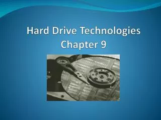
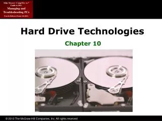
Hard Drive Technologies Chapter 9
Overview • In this chapter, you will learn to • Explain how hard drives work • Identify and explain ATA hard drive interfaces • Identify and explain SCSI hard drive interfaces • Describe how to protect data with RAID • Explain how to install drives • Configure CMOS and install drivers
Historical/Conceptual How Hard Drives Work
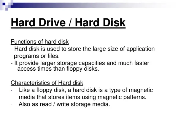
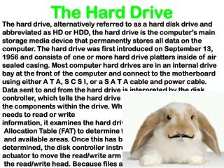
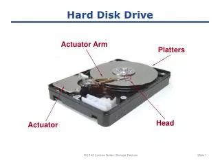
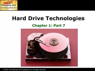
The Hard Drive • Hard drives are composed of individual disks or platters • The platters are made up of aluminum and coated with a magnetic medium • Two tiny read/write heads service each platter
The Hard Drive • The closer the read/write heads are to the platter, the more densely the data can be packed on to the drive • Hard drives use a tiny, heavily filtered aperture to equalize the air pressure between the exterior and interior of the hard drive • Platters spin between 3500 and 10,000 rounds per minute (RPM)
Data Encoding • Hard drives store data in tiny magnetic fields called fluxes • The flux switches back and forth through a process called flux reversal • Hard drives read these flux reversals at a very high speed when accessing or writing data • Fluxes in one direction are read as 0 and the other direction as 1
Data Encoding • Encoding methods used by hard drives are • Run length limited (RLL) • Data is stored using “runs” that are unique patterns of ones and zeroes • Can have runs of about seven fluxes • Partial Response Maximum Likelihood (PRML) • Uses a powerful, intelligent circuitry to analyze each flux reversal • Can have runs of about 16 to 20 fluxes • Significantly increased capacity (up to 1 TB)
Arm Movement in the Hard Drive • The stepper motor technology and the voice coil technology are used for moving the actuator arm • Moves the arms in fixed increments or steps • Only seen in floppies today • The voice coil technology uses a permanent magnet surrounding the coil on the actuator arm to move the arm • Automatically parks drive over non-data area when power removed
Geometry • Geometry is used to determine the location of the data on the hard drive • CHS (cylinders, heads, sectors) • Used to be critical to know geometry • Had to enter into CMOS manually • Today, geometry stored on hard drive • BIOS can query hard drive for geometry data
Heads • Heads • Number of read/write heads used by the drive to store data • Two heads per platter (top and bottom) • Most hard drives have an extra head or two for their own usage, so the number may not be even
Cylinders • Cylinders • Group of tracks of the same diameter going completely through the drive
Sectors per Track • Sectors per track • Number of slices in the hard drive • 512 bytes per sector
Obsolete Geometry • Might see in older systems • Write precompensation cylinder • The specific cylinder from where the drive would start writing data farther apart • Internal sectors physically smaller • External sectors physically larger • This identified cylinder where spacing changed • Landing zone • Unused cylinder as “parking place” for heads • Referred to as Lzone, LZ, Park • Needed for older drives using stepper motors
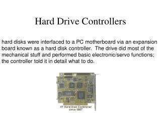
IT Technician CompTIA A+Essentials ATA—The King
Hard Drive Interfaces • ATA interfaces dominate today’s market • Many changes throughout years • Parallel ATA (PATA) historically prominent • Serial ATA (SATA) since 2003 • Small Computer System Interface (SCSI) • Pronounced “Scuzzy” • Used in many high-end systems
ATA-1 • Programmable I/O (PIO)—traditional data transfer • 3.3 MBps to 8.3 MBps • DMA—direct memory access • 2.1 MBps to 8.3 MBps • Allowed two drives (one master, one slave)
ATA-2 • Commonly called EIDE (though a misnomer) • Added second controller to allow for four drives instead of only two • Increased size to 8.2 GB • Added ATAPI • Could now use CD drives
ATA-3 • Self-Monitoring Analysis and Reporting Technology • S.M.A.R.T. • No real change in other stats
ATA-4 • Introduced Ultra DMA Modes • Ultra DMA Mode 0: 16.7 MBps • Ultra DMA Mode 1: 25 MBps • Ultra DMA Mode 2: 33 MBps • Ultra DMA Mode 2 also called ATA/33
INT13 Extensions • ATA-1 standard actually written for hard drives up to 137 GB • BIOS limited it to 504 MB due to cylinder, head, and sector maximums • ATA-2 implemented LBA to fool the BIOS, allowing drives to be as big as 8.4 GB • INT13 Extensions extended BIOS commands • Allowed drives as large as 137 GB
ATA-5 • Introduced newer Ultra DMA Modes • Ultra DMA Mode 3: 44.4 MBps • Ultra DMA Mode 4: 66.6 MBps • Ultra DMA Mode 4 also called ATA/66 • Used 40-pin cable, but had 80 wires • Blue connector—to controller • Gray connector—slave drive • Black connector—master drive ATA/66 cable
ATA-6 • “Big Drives” introduced • Replaced INT13 & 24-bit LBA to 48-bit LBA • Increased maximum size to 144 PB • 144,000,000 GB • Introduced Ultra DMA 5 • Ultra DMA Mode 5: 100 MBps ATA/100 • Used same 40-pin, 80-wire cables as ATA-5
ATA-7 • Introduced Ultra DMA 6 • Ultra DMA Mode 6: 133 MBps ATA/133 • Used same 40-pin, 80-wire cables as ATA-5 • Didn’t really take off due to SATA’s popularity • Introduced Serial ATA (SATA) • Increased throughput to 150 MBps to 300 MBps
IT Technician CompTIA A+Technician ATA-7
Serial ATA • Serial ATA (SATA) creates a point-to-point connection between the device and the controller • Hot-swappable • Can have as many as eight SATA devices • Thinner cables resulting in better airflow and cable control in the PC • Maximum cable length of 39.4 inches compared to 18 inches for PATA cables
Serial ATA • More on SATA • PATA device my be connected to SATA using a SATA bridge • Can have as many as eight SATA devices • Add more SATA functionality via a PCI card • eSATA • External SATA • Extends SATA bus to external devices eSATA Port
SCSI • Pronounced “Scuzzy” • Been around since ’70s • Devices can be internal or external • Historically the choice for RAID • Faster than PATA • Could have more than four drives • SATA replacing SCSI in many applications
SCSI Chains • A SCSI chain is a series of SCSI devices working together through a host adapter • The host adapter is a device that attaches the SCSI chain to the PC • All SCSI devices are divided into internal and external groups • The maximum number of devices, including the host adapter, is 16
Internal Devices • Internal SCSI devices are installed inside the PC and connect to the host adapter through the internal connector • Internal devices use a 68-pin ribbon cable • Cables can be connected to multiple devices
External Devices • External SCSI devices are connected to host adapter to external connection of host adapter • External devices have two connections in the back, to allow for daisy-chaining • A standard SCSI chain can connect 15 devices, including the host adapter
SCSI IDs • Each SCSI device must have a unique SCSI ID • The values of ID numbers range from 0 to 15 • No two devices connected to a single host adapter can share the same ID number • No order for the use of SCSI IDs, and any SCSI device can have any SCSI ID
SCSI IDs • The SCSI ID for a particular device can be set by configuring jumpers, switches, or even dials • Use your hexadecimal knowledge to set the device ID • Device 1 = 0 0 0 1 Off, Off, Off, On • Device 7 = 0 1 1 1 Off, On, On, On • Device 15 = 1 1 1 1 On, On, On, On • Host adapters often set to 7 or 15 but can be changed
Termination • Terminators are used to prevent a signal reflection that can corrupt the signal • Pull-down resistors are usually used as terminators • Only the ends of the SCSI chains need to be terminated • Most manufacturers build SCSI devices that self-terminate
Protecting Data • The most important part of a PC is the data it holds • Companies have gone out of business because of losing data on hard drives • Hard drives will eventually develop faults • Fault tolerance allows systems to operate even when a component fails • Redundant Array of Inexpensive Disks (RAID) is one such technology
RAID Level 0 • Disk striping • Writes data across multiple drives at once • Requires at least two hard drives • Provides increased read and writes • Not fault tolerant • If any drive fails, the data is lost
RAID Level 1 • Disk mirroring/duplexing is the process of writing the same data to two drives at the same time • Requires two drives • Produces an exact mirror of the primary drive • Mirroring uses the same controller • Duplexing uses separate controllers
RAID Levels 2 to 4 • RAID 2 • Disk striping with multiple parity drives • Not used • RAID 3 and 4 • Disk striping with dedicated parity • Dedicated data drives and dedicated parity drives • Quickly replaced by RAID 5
RAID Level 5 • Disk striping with distributed parity • Distributes data and parity evenly across the drives • Requires at least three drives • Most common RAID implementation Software-based RAID 5
0 0 1 0 1 0 1 0 0 1 1 1 Data Data Parity RAID 5 (Stripe with Parity)
RAID Level 6 • Super disk striping with distributed parity • RAID 5 with asynchronous and cached data capability
Implementing RAID • SCSI has been the primary choice in the past • Faster than PATA • PATA allowed only four drives • SATA today viewed as comparable choice • Speeds comparable to SCSI • Dedicated SATA controllers can support up to 15 drives
Hardware vs. Software • Hardware RAID • Dedicated controller • Operating system views it as single volume • Software RAID • Operating system recognizes all individual disks • Combines them together as single volume
Personal RAID • ATA RAID controller chips have gone down in price • Some motherboards are now shipping with RAID built-in • The future is RAID • RAID has been around for 20 years but is now less expensive and moving into desktop systems
Connecting Your Drive • Choosing your drive • PATA, SATA, or SCSI • Check BIOS and motherboard for support • Jumpers and cabling on PATA • Master • Slave • Cable select
Connecting SCSI Drives • First need compatible controller • Different types of SCSI • Connect data cable • Reversing this cable can damage drive, data, or both • Connect power • Pin 1 goes to Pin 1 • Configure SCSI IDs on drives and controller