Download
1 / 56
560 likes | 742 Vues
ISIS Symmetry Congress 2001. Symmetries on the Sphere Carlo H. Séquin University of California, Berkeley. Outline. 2 Tools to design / construct artistic artefacts: “Escher Balls”: Spherical Escher Tilings “Viae Globi”: Closed Curves on a Sphere Discuss the use of Symmetry

E N D
ISIS Symmetry Congress 2001 Symmetries on the Sphere Carlo H. Séquin University of California, Berkeley
Outline 2 Tools to design / construct artistic artefacts: • “Escher Balls”: Spherical Escher Tilings • “Viae Globi”: Closed Curves on a Sphere • Discuss the use ofSymmetry • Discuss Symmetry-Breakingin order to obtain artistically more interesting results.
Spherical Escher Tilings Jane YenCarlo SéquinUC Berkeley [1] M.C. Escher, His Life and Complete Graphic Work
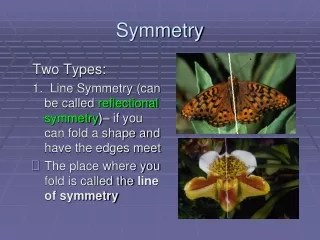
Introduction M.C. Escher • graphic artist & print maker • myriad of famous planar tilings • why so few 3D designs? [2] M.C. Escher: Visions of Symmetry
Spherical Tilings • Spherical Symmetry is difficult • Hard to understand • Hard to visualize • Hard to make the final object [1]
Our Goal • Develop a system to easily design and manufacture “Escher spheres” = spherical balls composed of identical tiles. • Provide visual feedback • Guarantee that the tiles join properly • Allow for bas-relief decorations • Output for manufacturing of physical models
[1] Interface Design • How can we make the system intuitive and easy to use? • What is the best way to communicate how spherical symmetry works?
R3 R5 R3 R3 R5 R2 Spherical Symmetry • The Platonic Solids tetrahedron octahedron cube dodecahedron icosahedron
Introduction to Tiling • Spherical Symmetry - defined by 7 groups • 1) oriented tetrahedron 12 elem: E,8C3, 3C2 • 2) straight tetrahedron 24 elem: E, 8C3, 3C2, 6S4, 6sd • 3) double tetrahedron 24 elem: E, 8C3, 3C2, i, 8S4, 3sd • 4) oriented octahedron/cube 24 elem: E, 8C3, 6C2, 6C4,3C42 • 5) straight octahedron/cube 48 elem: E, 8C3, 6C2, 6C4, 3C42, i, 8S6, 6S4, 6sd, 6sd • 6) oriented icosa/dodecah. 60 elem: E, 20C3, 15C2, 12C5,12C52 • 7) straight icosa/dodecah. 120 elem: E, 20C3, 15C2, 12C5, 12C52, i, 20S6, 12S10, 12S103, 15s Platonic Solids: 1,2) 4,5) 6,7) With duals: 3)
R3 R3 R2 R2 R2 R3 R3 R3 How the Program Works • Choose symmetry based on a Platonic solid • Choose an initial tiling pattern to edit = starting place Example: Tetrahedron R3 R2 Tile 2 Tile 1
Using an Initial Tiling Pattern • Easier to understand consequences of moving points • Guarantees proper tiling • Requires user to select the “right” initial tile [2] Tile 2 Tile 1 Tile 2
Modifying the Tile • Insert and move boundary points • system automatically updates the tile based on symmetry • Add interior detail points
Adding Bas-Relief • Stereographically project and triangulate: • Radial offsets can be given to points: • individually or in groups • separate mode from editing boundary points
Creating a Solid • The surface is extruded radially • inward or outward extrusion, spherical or detailed base • Output in a format for free-form fabrication • individual tiles or entire ball
Fused Deposition ModelingZ-Corp 3D Color Printer • - parts are made of plastic - starch powder glued together • each part is a solid color - parts can have multiple colors • => assembly Several Fabrication Technologies • Both are layered manufacturing technologies
Fused Deposition Modeling moving head inside the FDM machine support material
3D-Printing (Z-Corporation) infiltration de-powdering
R3 R3 R2 R2 R2 R3 R3 R3 12 Lizard Tiles (FDM) Pattern 1 Pattern 2
12 Fish Tiles (4 colors) FDM Hollow, hand-assembled Z-Corp Solid monolithic ball
24 Bird Tiles FDM2-color tiling Z-Corp 4-color tiling
Tiles Spanning Half the Sphere FDM4-color tiling Z-Corp 6-color tiling
Hollow Structures FDM Hard to remove the support material Z-Corp Blow loose powder from eye holes
Frame Structures FDM Support removal tricky, but sturdy end-product Z-Corp Colorful but fragile
60 Highly Interlocking Tiles 3D Printer Z-Corp.
PART 2: “Viae Globi”(Roads on a Sphere) • Symmetrical, closed curves on a sphere • Inspiration: Brent Collins’ “Pax Mundi”
Sculptures by Naum Gabo Pathway on a sphere: Edge of surface is like seam of tennis ball; ==> 2-period Gabo curve.
2-period Gabo curve • Approximation with quartic B-splinewith 8 control points per period,but only 3 DOF are used.
3-period Gabo curve Same construction as for 2-period curve
“Pax Mundi” Revisited • Can be seen as:Amplitude modulated, 4-period Gabo curve
SLIDE-UI for “Pax Mundi” Shapes Good combination of interactive 3D graphicsand parameterizable procedural constructs.
FDM Part with Support as it comes out of the machine
“Viae Globi” Family (Roads on a Sphere) 2 3 4 5 periods
2-period Gabo sculpture • Looks more like a surface than a ribbon on a sphere.
Via Globi 3 (Stone) Wilmin Martono
Via Globi 5 (Wood) Wilmin Martono
Via Globi 5 (Gold) Wilmin Martono
More Complex Pathways • Tried to maintain high degree of symmetry, • but wanted higly convoluted paths … • Not as easy as I thought ! • Tried to work with Hamiltonian pathson the edges of a Platonic solid,but had only moderate success. • Used free-hand sketching with C-splines, • then edited control vertices coordinatesto adhere to desired symmetry group.
“Viae Globi” • Sometimes I started by sketching on a tennis ball !
A Better CAD Tool is Needed ! • A way to make nice curvy paths on the surface of a sphere:==> C-splines. • A way to sweep interesting cross sectionsalong these spherical paths:==> SLIDE. • A way to fabricate the resulting designs:==> Our FDM machine.
“Circle-Splines” (SIGGRAPH 2001) Carlo Séquin Jane Yen On the plane -- and on the sphere
Defining the Basic Path Shapes Use Platonic or Archimedean solids as “guides”: • Place control points of an approximating spline at the vertices, • or place control points of an interpolating spline at edge-midpoints. • Spline formalism will do the smoothing. • Maintain some desirable degree of symmetry, • and make sure that curve closes – difficult ! • Often leads to the same basic shapes again …
Hamiltonian Paths Strictly realizable only on octahedron! Gabo-2 path. Pseudo Hamiltonian path (multiple vertex visits) Gabo-3 path.
Another Conceptual Approach • Start from a closed curve, e.g., the equator • And gradually deform it by introducing twisting vortex movements:
“Maloja” -- FDM part • A rather winding Swiss mountain pass road in the upper Engadin.
“Stelvio” • An even more convoluted alpine pass in Italy.
“Altamont” • Celebrating American multi-lane highways.
“Lombard” • A very famous crooked street in San Francisco • Note that I switched to a flat ribbon.
Varying the Azimuth Parameter Setting the orientation of the cross section … … using torsion-minimization with two different azimuth values … by Frenet frame