Download
1 / 37
370 likes | 779 Vues
HoleChart. Hole Chart Creation in “CoCreate Modeling”. April 2009. Main Features. Hole Chart based on both 3D and 2D information All hole types (machining, non-machining, user defined) Non-full-circular faces (pocket blends) Predefined descriptions

E N D
HoleChart Hole Chart Creationin “CoCreate Modeling” April 2009
Main Features • Hole Chart based on both 3D and 2D information • All hole types (machining, non-machining, user defined) • Non-full-circular faces (pocket blends) • Predefined descriptions • Creation and processing of wire erosion starting holes • No data loss at re-generation (user editing not necessary) • Supports rotated views and rotated reference axis • Filters for hole groups • Supports both visible and invisible holes • Exclude and include holes • Custom hole definitions • Highly customizable • Supports tolerance of positions • Supports reuse of standartized shop floor CNC programmes • Teach-In holes • Supports both metric and inch units • and most of all ...
Automatic – manual editing of the chart is not necessary ! We attach and extract all the necessary information from the 3D model. Subsequent updates of the Hole Chart goes very fast !
3D is the ’master’ model • A 2D view alone is not enough to take circles as holes. Only 3D model can give all the necessary information about the hole topology. On the following model all 3 features deliver the same 2D view but only one of them is a counterbore hole !
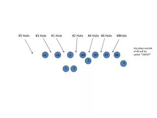
Question Which one of the below circles on the annotation view belongs to a counterhole bore?
Only the first one is coming from a counterbore hole. The other two – even looking exactly the same in the 2D drawing – are not counterboreholes ! Middle one is not even a hole ! That’s why we should look at the 3d model, to get extra information about the holes !
Which information do we need from the 3D Model ? • Does the 2D circle at all belong to a hole ? • Which 2D circles together belong to this hole ? • What is the type of the hole ? • What are hole parameters ?
Analyze or not ? • If holes are created by Machining, there is no need to analyze ! Machining Holes already have all the information attached. For holes not created with Machining, before we create the hole chart we should use the built-in Analyze function to get 3d topology information of the hole.
Different hole types • Standard holes created by CoCreate’s built-in Machining module • Custom made holes created by CoCreate’s built-in Machining module • Holes created by other packages (SolidGenius, PartLibrary or macros made by user) as a feature • Holes created simply by milling,boring and punching All of those types – even mixed on the same model – can be processed by HoleChart.
Machining Holes For holes created by Machining all the parameters are available. All the faces which together build the hole feature are known.
Non-Machining Holes build as a feature • All the faces which together build the hole feature are known. From these user defined Feautures all parameters could be interrogated
Non-Machining Holes build by punching and milling • Neither the faces which together build the hole feature nore the hole type can be inquired from the 3D model.
Text in the description column Text entry in the ’Description’ column of the hole chart can be put by 2 ways : • Manually by the user • Automatically by analyzing the hole geometry
Manual Editing • Although users can also enter the hole description manually , automatic output is the preferred method because manual entry will be lost each time hole chart is newly generated
Description Text for Machining holes Description text for a machining hole is put together from 2 parts
Customızations for the Machining Operations The customizing file for machining operation names is [SolidGenius]/Holechart/Message/English/machining_names.txt "MACH_ADV_LIBRARY_PARTIALLY_THREADED_BLINDHOLE" "Partially threaded blind" "MACH_ADV_LIBRARY_BLINDHOLE" "Blindhole" "MACH_ADV_LIBRARY_COUNTERSUNK_BLINDHOLE" "C-Sunk Blindhole" "MACH_ADV_LIBRARY_COUNTERSUNK_FLAT_BLINDHOLE" "C-Sunk Flat Blindhole" "MACH_ADV_LIBRARY_COUNTERSUNK_PARTIALLY_TOLERANCED_BLINDHOLE" "C-Sunk Tol. Blindhole" "MACH_ADV_LIBRARY_COUNTERSUNK_PARTIALLY_TOLERANCED_FLAT_BLINDHOLE" "C-Sunk Tol. Flat Blindhole" "MACH_ADV_LIBRARY_FLAT_BLINDHOLE" "Flat Blindhole"
Modification of description texts For advanced users, it is even possible to re-define the description text completely – without limitation !
Description Texts for Non-Machining holes You should first analyze Non-Machining holes to catogorize them in groups of : • simple holes • counterbore holes • countersink holes • threaded holes • other holes For each group there is again a user customizable predefined text and a parameter section
Tolerance of Position • Although a very important issue in mold & die design, there is no way of specifying tolerance for hole positions created by the Machining module.In traditional hole chart programmes, the tolerances for positions are added to the hole chart manually.
Name includes tolerance • By using a predefined pattern for Machining hole name, you can specify the tolerance of position for each Machining hole. XXXXyyyy XXXX ... Title - Type of hole Yyyy ...Tolerance of position
Why naming ? • Another way would have been attaching invisible tolerance information to the Machining hole.But the naming method is preferred because user can see the tolerances without any additional inquiry directly in the structure browser
Why title ? • On the shop level, you might want to prepare standard CNC programmes for different types of holes. • Process planners can benefit from standard holes types. Below some examples : THH7 ...Through hole with tolerance H7BHAB ...Blind hole with certain fitting tolerances
Sorting • Next to standard sortings in X, Y , Diameter and hole type there is also an ”user defined sorting” algorithm. • This is a combination of columns ”Hole Type” ”Dia” ”x” and ”y” and helps on the shop floor to manufacture group of holes with the same CNC program.
Custom Holes • Custom made holes can be recognized manually by face selection or automatically by the ”teach-in” method.
Custom Holes They appear in the hole chart with a customizable description text
Exclude Holes You can exclude any hole from the hole chart.
Include Holes • Normally hole chart would only consider 360 ° circles on the drawing and ignore partial arcs. • But if you wish so, you can also “include” individual arcs – like pocket corners - into the chart. They will be listed with a user defined description text.
To filter groups of holes • You can define different hole groups and show on/off individual groups in the hole chart..
Customized Descriptions • Automatic description of individual holes ( Machining and Non-machining ) can be overwritten by declaring them as ”custom holes” and entering a new description.
Starting Holes for wire eroded pockets • Many times, you might want to include also wire erosion starting holes into the hole chart as they have to be drilled as well. • Because starting holes are ”lose” cylinders and many users do not want to create an assembly HoleChart has special functions to create ”wire erosion holes attached as attributes” to the part. • In the structure browser the part still is a single object but starting holes can be switched on/off and transfered to the Annotation anytime. • In the Hole chart they are automatically distinguished and marked as ”Wire Erosion Starting Holes”
Position Numbers • Position numbers can be put automatically to each hole on the drawing. • User is free to edit the position number location on the drawing. • In subsequent update operations the location of the position numbers are kept.
Export Hole Chart • You can export the hole chart to a text file. • This file can be imported to Excel directly
Availability HoleChart is available for CoCreate Versions 14, 15, 16 and 17 Price 300 EUR or 600 EUR together with SolidGenius
Other MIP solutions ProgressivePower SolidGenius • SpaceCable • SpaceExtrusion • SpacePipe • ProgressivePower • OperationManager OperationManager SpaceExtrusion SpaceCable SpacePipe MIP applications are extending “CoCreate Modeling” with additional solutions from concept to manufacturing