Efficient Structural Design Philosophies Overview
230 likes | 346 Vues
Understand the principles behind Understrength Overload, Allowable Stress Design, Plastic Design, and Load and Resistance Factor Design to ensure the required strength is achieved. Explore AISC philosophies and LRFD criteria for structural safety.

Efficient Structural Design Philosophies Overview
E N D
Presentation Transcript
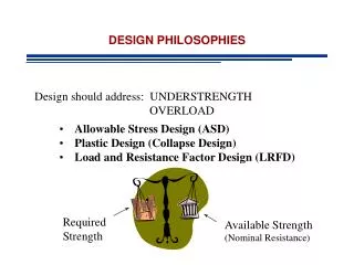
DESIGN PHILOSOPHIES Design should address: UNDERSTRENGTH OVERLOAD • Allowable Stress Design (ASD) • Plastic Design (Collapse Design) • Load and Resistance Factor Design (LRFD) Required Strength Available Strength (Nominal Resistance)
Allowable Stress Design (ASD) - AISCS 1923 Philosophy: Maximum stress must not exceed allowable stress Fmax : maximum stresses due to working loads Fall : allowable stresses F.S. : Factor of Safety > 1 (understrength) Flim: Limit of Usefulness (FyFuFcr etc) Can be expressed in terms of Strength
Allowable Stress Design (ASD) Comments • Real Safety Against Failure is Unknown • Conservative • One Load Factor for All Load Types
Plastic Design (PD) - AISCS 1963 Takes Advantage of Ductility and Ultimate Strength Philosophy:Limit of Structural Usefulness is load Pu that causes a plastic mechanism to form Failure Load Reaches failure under factored loads but safe under service loads
Load and Resistance Factor Design (LRFD) - 1986 Makes full use of test information, design experience, engineering judgment Probabilistic Analysis Limit State: Describe a condition at which a structure or part of it ceases to perform the intended function
Load and Resistance Factor Design (LRFD) - 1986 • Typical Strength Limit States • Plastic Strengths • Buckling • Fracture • Fatigue • Overturning • Typical Serviceability Limit States (under normal service loads) • Excessive Deflections • Slipping • Vibrations • Cracking • Deterioration
Load and Resistance Factor Design (LRFD) - 1986 For Each Limit State LRFD Satisfies Rn : nominal resistance Qi : applied loads f : resistance factor < 1 (understrength) g : load factor > 1 (overload)
AISC Manual • AISC Specification • Design Aids • Catalog of most widely available structural shapes • Editions 1-9 ->ASD • Editions 10, 11, 12 -> LRFD Edition 1, 2, 3 • Current Edition 13 incorporates ASD and LRFD
AISC Manual • Part 1 – Dimensions and Properties • Part 2 – General Design Considerations • Part 3 – Design of Flexural members • Part 4 – Design of Compression Members • Part 5 – Design of Tension Members • Part 6 – Design of Members Subject to Combined Loading • Parts 7 to 15 – Connections • Part 16 Specifications and Codes • Part 17 Misc. Data and Mathematical Information
AISC Specifications (PART 16 of Manual) • Main Body • Alphabetically organized to chapters A-M • Major Headings labeled with chapter designation followed by number • Further subdivisions are numerically labeled • Appendices • Appendices 1-7 • Commentary • Background and elaboration on provisions of the Specification. • Organized in the same way as the specification
Design RequirementsSpecifications - Chapter B • B1 General Provisions • B2 Loads and Load Combinations (LRFD or ASD) • Applicable building codes • In the absence use SEI/ASCE 7 • B3 Design Basis • B3.1 Required Strength: Required strength determined by structural analysis based on load combinations • B3.2 Limit State: No applicable strength or serviceability limit state shall be exceeded when structure subjected to all load combinations • B3.3 Design for Strength Using LRFD • B3.4 Design for Strength Using ASD • B3.5 Design for Stability • etc
Design for Strength ASD LRFD
Load Combinations - LRFD • Manual – Part 2 page 2-8 for LRFD
Load Combinations - ASD • Manual – Part 2 page 2-9 for ASD
Resistance Factorsf(Manual pp. 2-9) LRFD f=0.9 for limit states involving yielding f=0.75 for limit states involving rupture ASD W=1.67 for limit states involving yielding W=2.0 for limit states involving rupture
LRFD – Probabilistic Approach Structural Safety: Acceptably small probability of Q (demand) exceeding R (resistance) Load and Resistance Factors assure that probability is negligibly small
LRFD - Design Criteria b: Safety Index or reliability index The larger the safer
LRFD - Design Criteria For Example
Example I A floor system has W24x55 sections spaced 8 ft on center supporting a dead load 50 psf and live load 80 psf. The W sections are simply supported. Determine nominal moment capacity 4’ 8’ 4’