Fundamentals of Microelectronics
670 likes | 1.07k Vues
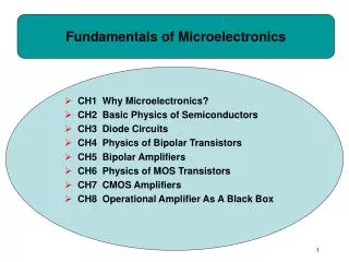
Fundamentals of Microelectronics. CH1 Why Microelectronics? CH2 Basic Physics of Semiconductors CH3 Diode Circuits CH4 Physics of Bipolar Transistors CH5 Bipolar Amplifiers CH6 Physics of MOS Transistors CH7 CMOS Amplifiers CH8 Operational Amplifier As A Black Box.

Fundamentals of Microelectronics
E N D
Presentation Transcript
Fundamentals of Microelectronics • CH1 Why Microelectronics? • CH2 Basic Physics of Semiconductors • CH3 Diode Circuits • CH4 Physics of Bipolar Transistors • CH5 Bipolar Amplifiers • CH6 Physics of MOS Transistors • CH7 CMOS Amplifiers • CH8 Operational Amplifier As A Black Box
Chapter 3 Diode Circuits • 3.1 Ideal Diode • 3.2 PN Junction as a Diode • 3.3 Applications of Diodes
Diode Circuits • After we have studied in detail the physics of a diode, it is time to study its behavior as a circuit element and its many applications. CH3 Diode Circuits
Diode’s Application: Cell Phone Charger • An important application of diode is chargers. • Diode acts as the black box (after transformer) that passes only the positive half of the stepped-down sinusoid. CH3 Diode Circuits
Diode’s Action in The Black Box (Ideal Diode) • The diode behaves as a short circuit during the positive half cycle (voltage across it tends to exceed zero), and an open circuit during the negative half cycle (voltage across it is less than zero). CH3 Diode Circuits
Ideal Diode • In an ideal diode, if the voltage across it tends to exceed zero, current flows. • It is analogous to a water pipe that allows water to flow in only one direction. CH3 Diode Circuits
Diodes in Series • Diodes cannot be connected in series randomly. For the circuits above, only a) can conduct current from A to C. CH3 Diode Circuits
IV Characteristics of an Ideal Diode • If the voltage across anode and cathode is greater than zero, the resistance of an ideal diode is zero and current becomes infinite. However, if the voltage is less than zero, the resistance becomes infinite and current is zero. CH3 Diode Circuits
Anti-Parallel Ideal Diodes • If two diodes are connected in anti-parallel, it acts as a short for all voltages. CH3 Diode Circuits
Diode-Resistor Combination • The IV characteristic of this diode-resistor combination is zero for negative voltages and Ohm’s law for positive voltages. CH3 Diode Circuits
Diode Implementation of OR Gate • The circuit above shows an example of diode-implemented OR gate. • Vout can only be either VA or VB, not both. CH3 Diode Circuits
Input/Output Characteristics • When Vin is less than zero, the diode opens, so Vout = Vin. • When Vin is greater than zero, the diode shorts, so Vout = 0. CH3 Diode Circuits
Diode’s Application: Rectifier • A rectifier is a device that passes positive-half cycle of a sinusoid and blocks the negative half-cycle or vice versa. • When Vin is greater than 0, diode shorts, so Vout = Vin; however, when Vin is less than 0, diode opens, no current flows thru R1, Vout = IR1R1 = 0. CH3 Diode Circuits
for for Signal Strength Indicator • The averaged value of a rectifier output can be used as a signal strength indicator for the input, since Vout,avg is proportional to Vp, the input signal’s amplitude. CH3 Diode Circuits
Diode’s application: Limiter • The purpose of a limiter is to force the output to remain below certain value. • In a), the addition of a 1 V battery forces the diode to turn on after V1 has become greater than 1 V. CH3 Diode Circuits
Limiter: When Battery Varies • An interesting case occurs when VB (battery) varies. • Rectification fails if VB is greater than the input amplitude. CH3 Diode Circuits
Different Models for Diode • So far we have studied the ideal model of diode. However, there are still the exponential and constant voltage models. CH3 Diode Circuits
Input/Output Characteristics with Ideal and Constant-Voltage Models • The circuit above shows the difference between the ideal and constant-voltage model; the two models yield two different break points of slope. CH3 Diode Circuits
Input/Output Characteristics with a Constant-Voltage Model • When using a constant-voltage model, the voltage drop across the diode is no longer zero but Vd,on when it conducts. CH3 Diode Circuits
Another Constant-Voltage Model Example • In this example, since Vin is connected to the cathode, the diode conducts when Vin is very negative. • The break point where the slope changes is when the current across R1 is equal to the current across R2. CH3 Diode Circuits
Exponential Model • In this example, since the two diodes have different cross-section areas, only exponential model can be used. • The two currents are solved by summing them with Iin, and equating their voltages. CH3 Diode Circuits
Another Constant-Voltage Model Example • This example shows the importance of good initial guess and careful confirmation. CH3 Diode Circuits
Ix Cell Phone Adapter • Vout = 3 VD,on is used to charge cell phones. • However, if Ix changes, iterative method is often needed to obtain a solution, thus motivating a simpler technique. CH3 Diode Circuits
Small-Signal Analysis • Small-signal analysis is performed around a bias point by perturbing the voltage by a small amount and observing the resulting linear current perturbation. CH3 Diode Circuits
Small-Signal Analysis in Detail • If two points on the IV curve of a diode are close enough, the trajectory connecting the first to the second point is like a line, with the slope being the proportionality factor between change in voltage and change in current. CH3 Diode Circuits
Small-Signal Incremental Resistance • Since there’s a linear relationship between the small signal current and voltage of a diode, the diode can be viewed as a linear resistor when only small changes are of interest. CH3 Diode Circuits
Small Sinusoidal Analysis • If a sinusoidal voltage with small amplitude is applied, the resulting current is also a small sinusoid around a DC value. CH3 Diode Circuits
Cause and Effect • In (a), voltage is the cause and current is the effect. In (b), the other way around. CH3 Diode Circuits
Adapter Example Revisited • With our understanding of small-signal analysis, we can revisit our cell phone charger example and easily solve it with just algebra instead of iterations. CH3 Diode Circuits
Simple is Beautiful • Inthis example we study the effect of cell phone pulling some current from the diodes. Using small signal analysis, this is easily done. However, imagine the nightmare, if we were to solve it using non-linear equations. CH3 Diode Circuits
Applications of Diode CH3 Diode Circuits
Half-Wave Rectifier • A very common application of diodes is half-wave rectification, where either the positive or negative half of the input is blocked. • But, how do we generate a constant output? CH3 Diode Circuits
Diode-Capacitor Circuit: Constant Voltage Model • If the resistor in half-wave rectifier is replaced by a capacitor, a fixed voltage output is obtained since the capacitor (assumed ideal) has no path to discharge. CH3 Diode Circuits
Diode-Capacitor Circuit: Ideal Model • Note that (b) is just like Vin, only shifted down. CH3 Diode Circuits
Diode-Capacitor With Load Resistor • A path is available for capacitor to discharge. Therefore, Vout will not be constant and a ripple exists. CH3 Diode Circuits
Behavior for Different Capacitor Values • For large C1, Vout has small ripple. CH3 Diode Circuits
Peak to Peak amplitude of Ripple • The ripple amplitude is the decaying part of the exponential. • Ripple voltage becomes a problem if it goes above 5 to 10% of the output voltage. CH3 Diode Circuits
Maximum Diode Current • The diode has its maximum current at t1, since that’s when the slope of Vout is the greatest. • This current has to be carefully controlled so it does not damage the device. CH3 Diode Circuits
Full-Wave Rectifier • A full-wave rectifier passes both the negative and positive half cycles of the input, while inverting the negative half of the input. • As proved later, a full-wave rectifier reduces the ripple by a factor of two. CH3 Diode Circuits
The Evolution of Full-Wave Rectifier • Figures (e) and (f) show the topology that inverts the negative half cycle of the input. CH3 Diode Circuits
Full-Wave Rectifier: Bridge Rectifier • The figure above shows a full-wave rectifier, where D1 and D2 pass/invert the negative half cycle of input and D3 and D4 pass the positive half cycle. CH3 Diode Circuits
Input/Output Characteristics of a Full-Wave Rectifier (Constant-Voltage Model) • The dead-zone around Vin arises because Vin must exceed 2 VD,ON to turn on the bridge. CH3 Diode Circuits
Complete Full-Wave Rectifier • Since C1 only gets ½ of period to discharge, ripple voltage is decreased by a factor of 2. Also (b) shows that each diode is subjected to approximately one Vp reverse bias drop (versus 2Vp in half-wave rectifier). CH3 Diode Circuits
Current Carried by Each Diode in the Full-Wave Rectifier CH3 Diode Circuits
Summary of Half and Full-Wave Rectifiers • Full-wave rectifier is more suited to adapter and charger applications. CH3 Diode Circuits
Voltage Regulator • The ripple created by the rectifier can be unacceptable to sensitive load; therefore, a regulator is required to obtain a very stable output. • Three diodes operate as a primitive regulator. CH3 Diode Circuits
Voltage Regulation With Zener Diode • Voltage regulation can be accomplished with Zener diode. Since rd is small, large change in the input will not be reflected at the output. CH3 Diode Circuits
Line Regulation VS. Load Regulation • Line regulation is the suppression of change in Vout due to change in Vin (b). • Load regulation is the suppression of change in Vout due to change in load current (c). CH3 Diode Circuits
Evolution of AC-DC Converter CH3 Diode Circuits
Limiting Circuits • The motivation of having limiting circuits is to keep the signal below a threshold so it will not saturate the entire circuitry. • When a receiver is close to a base station, signals are large and limiting circuits may be required. CH3 Diode Circuits