Download
1 / 44
470 likes | 661 Vues
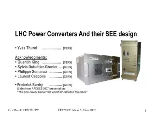
LHC Power Converters And their SEE design Yves Thurel ................... [CERN] Acknowledgments: Quentin King ................... [CERN] Sylvie Dubettier-Grenier .... [CERN] Philippe Semanaz ............. [CERN] Laurent Ceccone ............. [CERN ]

E N D
LHC Power Converters And their SEE design • Yves Thurel ................... [CERN] • Acknowledgments: • Quentin King ................... [CERN] • Sylvie Dubettier-Grenier .... [CERN] • Philippe Semanaz ............. [CERN] • Laurent Ceccone ............. [CERN] • Frederick Bordry ............. [CERN] Slides from RADECS 2007 presentation : “The LHC Power Converters and their radiation tolerance” CERN R2E School 2-3 June 2009
Introduction First, what to expect from a power converter engineer dealing with Single Event Effects design… Let’s have a look in detail and imagine a CERN Engineer visiting a Power Converter Company for a S.E.E compliant power converter for the LHC Upgrade Program... CERN R2E School 2-3 June 2009
But Now, you need the best for LHC Upgrade. You need HIGH TECHCONVERTERS!! Somewhere in 2009... Welcome to HOMPOWER and Sons!!! See my father’s 30 years old Converter design. No diagnostics. Control: ON-OFF switch. …Still running!!! Hum…well I assumed yes... CERN Infra RED + WiFi Remote Control + Internet Connection.. New Generation: XP5000Digital Processor control. 256 MB memory, Flashable BIOS over the NET. Can I Power it? Of course CERN R2E School 2-3 June 2009
OOPS!! Remote batteries dead ? Well? D’OH!! Itdoesn’t work!!! CERN OOPS...Its surely a firewall problem Itdoesn’t work better through the network... Well??? CERN CERN R2E School 2-3 June 2009
With all these microprocessors, did you integrate S.E.E in your design? well hum… it’s a lot of tiny energetic elements to deal with… OK OK OK OK!! ??!! SEE what?? Since at CERN for a longtime, I now only speakin acronyms ... CERN CERN If we re-design completely our converter including your SEE request from scratch...Is it OK? Too many years later... Well...Yes...Perfect!! CERN R2E School 2-3 June 2009
Same place in 2012... We re-designed the converter integrating a NEW S.E.E. RACK!!! By the way, do you provide us directly with your SEE “things” or do we fill the rack in the tunnel with them? CERN CERN R2E School 2-3 June 2009
What was SO wrong in the process??? Did you integrate SEE in your design? Too much simplified description of the problem for a SEE newbie Did you integrate in your design the high volume of tiny elements we will send to the power converters? I have to find a place in the power converter to store all the small things they have a lot at CERN Don’t simplify too much the S.E.E problematic. It is not simple and you have to be prepared to invest a lot of time to LEARN, TEACH what IT IS to people not used to. A good comprehension of the mechanism is the crucial 1st step. CERN R2E School 2-3 June 2009
Same Place in 2012... Moral and talk construction We re-designed the converter integrating NOW a S.E.E. RACK!!! • Power Converters are nowadays integrating a lot of « high performance digital » components: CPU, RAM… • Power Converter Specialists are not familiar at all with S.E.E concepts: WHAT IT IS!!, design key rules • Old Fashioned Power Converters were certainly more robust with respect to S.E.E problems • A « S.E.E. » design is long, costly and not always possible (Test infrastructure) • Even with good intentions, disaster is never far away for a « rad-tolerant » design, especially when using COTS components By the way, do you provide us directly with your S.E.E “things” or do we fill the rack in the tunnel with them? CERN R2E School 2-3 June 2009
Power Converter Power Converter Design Regarding Single Event Effect Issues* * See context Below • Hadron fluence • (E >20 MeV) • [cm-2] / year 103 104 105 106 107 108 109 1010 CNGS over 2 weeks Airplaneover 1 year Sea levelover 1 year LHC60Aover 1 year CERN R2E School 2-3 June 2009
CERN R2E School 2-3 June 2009 Power Converter Overview • How does a converter look like • From some kg up to thousands of kg • Electrical connections • A cooling system (water / air) • Digital Controller with a Control Field bus LHC13kA-180V2-Quadrant8 UnitsCERN Design LHC120A-10V4-Quadrant300 UnitsCERN Design LHC4..6kA-08V1-Quadrant200 UnitsKempower LHC60A-08V4-Quadrant730 UnitsCERN Design
Power Converter Architecture 1/3 • The basics • A Modern Converter is a “black box” which: • transform AC Mains Power into adequate conditioned power to the load • Is controllable over a field bus with advanced diagnostic features • Import and export data from and to the controls applications and database AC Mains Supply Iout Control Power Converter Load Status & meas Vout Databases • The Good Question in the case of a radiation-hard converter • How to manage the following required data processing of the converter • Remote control of the power converter (using Field Bus) • Accessing external database • Load Parameters for tuning Digital Control loop (database import) • Load operational Limits (current voltage) • Calibration parameters • Providing modern Post Mortem Analyze (database export) • On line status and analog measurements CERN R2E School 2-3 June 2009
Power Converter Architecture 2/3 • An adequate Answer (LHC Answer) • Architecture of the LHC power converter was divided in 3 parts: • Power conversion unit • Digital Control unit • High precisionmeasurement unit This unit does not require any trimming depending on load nature. No access to database required Iout Load ACMainsSupply • Power Part • (Voltage Source) • « Voltage amplifier » • LoadProtection Vout This unit concentrates all data processing, database request, import & export data, post mortem… A B digital.... analog Vref • Digital Electronic • Volt. Source Control • High Prec. Digital loop • Com. with LHC Control Sensorselectronic ControlWorldFip- I ref - I.A This unit can be pure analog sensor I.B AC Mains Supply AC Mains Supply CERN R2E School 2-3 June 2009
Power Converter Architecture 3/3 Entering the different parts • Component types • CPU, CPLD, DSP, RAM • Power Transistors & Drivers • Optocouplers • DC-DC, AC-DC • Traditional other circuits • Power Part • (Voltage Source) • « Volt. amplifier » • Load Protection • Radiation Impact • Not highly sensitive components like CPU or RAM • But High Power = danger / destruc. • Component types • CPU, CPLD, DSP, RAM, FPGA • Power Transistors & Drivers • Optocouplers • DC-DC, AC-DC • Traditional other circuits • Radiation Impact • Great care on this Unit since high concentration of sensitive components • Digital Electronic • Volt. Source Control • High Prec. Dig. loop • Communication • Radiation Impact • Standard analog components. No high potential risk • Component types • CPU, CPLD, DSP, RAM • Power Transistors & Drivers • Optocouplers • DC-DC, AC-DC • Traditional other circuits Sensorselectronic A B Not treated here since low S.E.E impact CERN R2E School 2-3 June 2009
Digital Controller The digital controller Design Iout Load ACMainsSupply Power Part (Voltage Source) - « Voltage amplifier » - Load Protection Vout A B digital.... analog Vref • Digital Electronic • Volt. Source Control • High Prec. Digital loop • Com. with LHC Control Sensorselectronic ControlWorldFip- I ref - I.A I.B AC Mains Supply AC Mains Supply CERN R2E School 2-3 June 2009
Control Unit Overview • How does a Digital Controller look like • Digital controller • Its PSUs • Its chassis collecting all signals exchangedwith power converter and field bus digital.... analog Vref • Digital Electronic • Volt. Source Control • High Prec. Digital loop • Com. with LHC Control ControlWorldFip- I ref - I.A I.B AC Mains Supply Electronic Chassis PSUsAC-DC and / or DC-DC) High Prec.Electronics cards CERN R2E School 2-3 June 2009
Digital Control Unit Architecture • Overview of hardware internal components layout • Main Processor: HC16 • internal RAM not used • DSP Co-Processor C32 • internal RAM not used • Memories • SEE Optimized • Adequate Technology compared to use • EDAC Corrections • Power Cycle • advanced feature: - Push button - User command - Magic (long) packet on WorldFip • Reset • advanced feature - Slow Watchdog - Fast Watchdog - User command CERN R2E School 2-3 June 2009
Digital Control Unit: Components - criteria 1/4 • Microcontroller MCU (MC68HC16) • Function: Communication, command parsing, logging • SEE sensitivity Internal Memory sensitive registers sensitive • Market & Choices COTS possible combined with testing • Fabrication technology • Core voltage dependence? (we used 5V devices) • SEE Improvement Use only component radiation tested & validated • Do not use internal memory (if no EDAC) • Only use registers (low cross section & less sensitive) • Refresh registers all the time • Program stored in Flash Memory • Dynamic Data stored in EDAC + SRAM • Slow & Fast Watchdog for reset • Power Cycle feature • Software Auto-check (code confidence & integrity test) CERN R2E School 2-3 June 2009
Digital Control Unit: Components – criteria 2/4 • DSP (TMS320C32) • Function: Real-time function generation and current regulation • SEE sensitivity Internal Memory sensitiveregisters sensitive • Market & Choices COTS possible combined with testing • Fabrication technology • Core voltage dependence? (we used 5V devices) • SEE Improvement Do not use internal memory (no EDAC) • Only use registers (low cross section) • Refresh registers all the time • Since used as a co-processor only => almost transparent • reset by MCU in case of corruption detection • Program and Dynamic Data stored in EDAC x SRAM CERN R2E School 2-3 June 2009
Digital Control Unit: Components - criteria 3/4 • CPLD • Function: Interlock state machine, Link between MCU & DSP and • their peripherals: memories, DACs, ADCs, I/Os • SEE sensitivity Code not considered as sensitive since stored in FLASH • Flip Flop Cells corruption • Market & Choices COTS possible combined with testing • Fabrication technology • Core voltage dependence? (we used 5V devices) • SEE Improvement Flip Flop Cells corruption solved where possible by synchronous logic only and triple logic with majority voting • FPGA • General approach SRAM based FPGAs are better not to be considered • Anti-fuse are good by not modifiable • Rad-tol reprogrammable FPGAs do now exist but • were not available when the FGC was being designed CERN R2E School 2-3 June 2009
Digital Control Unit: Components - criteria 4/4 • SRAM • Function: High Speed read & write Memories • Dynamic variables: internal and worldFip communication • regulation algorithm • SEE sensitivity High Sensitivity (non-EDAC ones) • Market & Choices COTS not possible, military possible but very expansive • SEE Improvement Use ONLY with EDAC • FRAM • Function: High Speed but Finite access Non Volatile RAM • Store Local constants imported from DATABASE • (Load parameters, operating limits…) • SEE sensitivity None • Market & Choices COTS (MRAM now preferred as non access limit) • FLASH • Function: High Speed read only Memories • Main Program and Constants for MCU and DSP storage • SEE sensitivity Low sensitivity • Market & Choices COTS • SEE Improvement CRC Control (boot) • Software Auto-check (code confidence & integrity test) CERN R2E School 2-3 June 2009
CERN R2E School 2-3 June 2009 Nbr ofErrors sSEU= Nbr of hadrons [cm-2] Digital Control Unit: SEE Impact on SRAM Example • LHC Tunnel Practical Example • How sensitiveìs an SRAM • What can be the effect on a large installation like CERN • CMOS Static RAM memory • 1 Meg: 128K x 8-Bit • 5 Volt • sseu= 10-8 cm-2 per device • 8 SRAM memory per Digital Controller1 Power Converter = 1 Digital Controller • 240 converters in RRs752 converters in Arcs • Let’s assume Radiation LevelRR : 1x 1008 hadrons/cm2 (E>20 MeV) per yearARCs: 4x 10¹⁰ hadrons/cm2 (E>20 MeV) per year Expected number of single event errors in SRAM : 240 x 8x10-8 x 1x108 2’000 errors / year = 10 / day ! 752 x 8x10-8 x 4x1010 25 x 105 errors / year = 10 / minute!!!
Digital Control Unit: Memories Remedies • Memory “hardware Map” * Dual port – also visible to C32 EDAC :Error Detection And Correction CERN R2E School 2-3 June 2009
Digital Control Unit: Analogue High Precision Constraints • When High Precision dictates its components • Function of the card: 2 ADC channels - 1 DAC channel • Analogue Medium Precision • Solution: RadTol tested COTS 16 bits ADC exists (LHC60A FGC) • Analogue High Precision • high performance ADCs are based on Sigma Delta design and require a digital filter based on a Xilinx Spartan 20 FPGA containing on 200 Kbits of corruptible SRAM • Solution: • Detect corruptions • 2 channels / converter(2 DCCTs + 2 ADCs) • Compare channels • Detect unphysical behaviour in the measured signals • Implement a Reset on analog filters to clear SEE corruptions (few 1ms) • (DAC stays frozen during reset: transparent for converter & operation) • Implement Power cycle on analogue card (1 ms)(DAC goes OFF, converter voltage goes down to 0V for ~2ms) CERN R2E School 2-3 June 2009
Digital Control Unit: Reset & Power Cycle Overview • Global Reset: Action taken in case corruption detected • Fast Watchdog • DescriptionCPLD checks that software interrupt within +/-200us window • Speed & Delay Trigger after 1.2ms – reset is 32ms later (time to log data) • Cause Software crash in main program due to any cause • SlowWatchdog • Description Simple monostable triggered by real-time OS context switch • Speed & Delay ~6s • Cause Software crash in boot program • User • Description Digital output under software control • Speed & Delay On request by operator command • Cause User requires a reset (e.g. for software update) • Multiple Bit Error • Speed & Delay immediate • Cause Multiple corrupted bits within 32-bit long data word • detected by EDAC protecting the SRAM • ConsequenceHC16 Reset + DAC frozen • => Converter doesn’t stop CERN R2E School 2-3 June 2009
Digital Control Unit: Reset & Power Cycle Overview • Global Power Cycle: Action taken in case corruption => Total Crash • CauseUser Request Only (sending magic (long) frames across WorldFip network) • MechanismUser requests that the gateway sends a sequence of • description long (256 byte) messages (max length normally is 128 bytes) • An analogue circuit detects the long messages and adds • charge to a leaky capacitor for every message received • If a threshold is exceeded a power cycle is triggered. • The threshold is lower if the FGC is in the boot (after a • crash) so crashed FGCs can be cycled separately to • operating systems. • Frame detection uses only the analogue FieldDrive device, • not the MicroFip interface. • Consequence Major Reboot trying to recover from major crash • => Converter stop CERN R2E School 2-3 June 2009
CERN R2E School 2-3 June 2009 Digital Control Unit: Radiation Test Campaigns – CERN TCC2 • CERN TCC2 (1999..2002) • A first radiation Experience for a lot of us. • Big size components can be tested. • Spectrum and Flux Not well known • Radiation not well characterized • T.I.D tests but what about S.E.E Results? • Summary of equipment tested • A lot of basic components (PSU, DCDCs…) were tested and are up to know still installed in final equipment • 1999 WorldFiP components • 2000 Memory and microcontroller • 2001 Analog component • 2002 Complete power converter • 2002 Digital Controller only • Critical components identified… • …but working ones limits and susceptibility is not really known. • Not sufficient to ensure Rad-Hard characteristics. SPS experimental zone: test beam
Digital Control Unit: Radiation Test Campaigns - Louvain • Louvain (2003) • Small beam size so only a few components • could be exposed at a time. • Mono-energetic beam (60MeV protons) • Well control flux and fluence • Very high flux (up to 0.7 Gray/s) • Quick tests (less than 15 minutes) • Current Consumption increase • SEU corruption Cross Section CERN R2E School 2-3 June 2009
Digital Control Unit: Radiation Test - Louvain Test Results • Total Integrated Dose Effects • All components were measured and qualified concerning the T.I.D. effect. • Single Event Upset • Protectable Items……………………….. External RAM 10-15 /bit/p/cm² • Unprotectable Items……………………. Xilinx CPLD latches 102 bits 10-13 /bit/p/cm² • Xilinx FPGA RAM 105 bits 10-13 /bit/p/cm² • Processor Registers 103 bits 10-13 /bit/p/cm² • Processor on-chip RAM (not used) 10-13 /bit/p/cm² • Effect On Large Installation (750 LHC Tunnel Power Converters) • Processor register corruptions WILL cause crashes, but calculation shows that: • S.E.U. MTBF…………..1-4 week(s) Standard MTBF”………………….1 week (some reset will be transparent) (100,000 hours MTBF / system = 5.5 days /750 syst.) CERN R2E School 2-3 June 2009
Digital Control Unit: Radiation Test Campaigns – CERN CNGS • CERN CNGS Gallery (2008) • Big size components can be tested. • LHC Tunnel conditions close to CNGS ones • Wide Energy spectrum, then less easy to analyse • Spectrum and Flux known and measured • A Great Parasitic Facilities ( but parasitic!!!) TSG45 Rack containing the 2 Digital Controllers TSG45 RADMON • Since CNGS irradiation conditions are wide energy spectrum, and complete system are tested, diagnostic is not easy, and is harder since this experiment is parasitic to CNGS operation. • An irradiated item can only be accessed and removed following CNGS planning. particules CERN R2E School 2-3 June 2009
Digital Control Unit: Radiation Test – CERN CNGS Test Results • RESULTS on 2 Digital Controllers tested • 7754 SEU counted on a FGC memories, all 100% corrected (EDAC) EDAC and memory corruption detection works…………………………….. • 120 Gy on a FGC, and no influence seen on components (Louvain showed that critical limit was below 120 Gy). CNGS = Louvain = Very good facilities (but parasitic!!)……………………… • 3-5 SEU on register C32 and HC16 (crash software if critical register) Software Update with corruption detection feature for 2009……………… • 6 Stops (slow watchdog detection) but auto-recovering resetting softwareAuto recovery system works……………………………………………………. • Analog Card High Precision Digital filter corrupted many times as expected showing the corruption process and major impact Soft Update with digital filter corruption detection feature for 2009…….. • 3 crashes not explained on both FGC + 1 Lethal crash for one but manual-recovering using hardware Power Cycle implemented feature each time except for final lethal crash on one FGC CPLD Single Event Destructive Latchup……………………………………… CERN R2E School 2-3 June 2009
Digital Control Unit: Radiation Test – CERN CNGS Test Results Single Event Destructive Latchup Reminder: Louvain Test: “only 13 CPLDs being tested” • Single Event Effects • Protectable Items……………………….. External RAM 10-15 /bit/p/cm² • Un-protectable Items…………………. Xilinx CPLD latches 102 bits 10-13 /bit/p/cm² • Xilinx FPGA RAM 105 bits 10-13 /bit/p/cm² • Processor Registers 103 bits 10-13 /bit/p/cm² • Processor on-chip RAM (not used) 10-13 /bit/p/cm² Actions: a 2009 CNGS Test campaign on 100 Xilinx CPLDs will gives the probability of such a destructive event. CERN R2E School 2-3 June 2009
Digital Control Unit: Radiation Test Campaigns – Prospero • Prospero (2009) • Source of Neutrons: Reactor • Big size components can be tested. • Mostly Mono-energetic neutron beam • 1MeV peak, 10MeV maximum • Fluence : 1.5x10⁻¹² neutrons/3h • SEU should be less visible with Only 1Mev neutron. Impact on analog devices is assumed, and degradation effects of these 1MeV neutron on die is expected… • SEU corruption Cross Section • Current Consumption increase measurement • Reference Voltage source CERN R2E School 2-3 June 2009
Digital Control Unit: Radiation Test – Prospero Test Results • RESULTS on 2 Digital Controllers tested • 1468 SEU counted on FGC external memories*, all 100% corrected EDAC and memory corruption detection works…………………………….. • No SEU on register C32 and HC16 • No SEU on Internal* RAM C32 and HC16 • No corruption on Analog Card High Precision Digital filter • Small Deviation (tolerable) on voltage references used for high precision 1-10MeV Neutron impact on Digital Controller is low………………..…… Comparison between CNGS and Prospero (different flux) • Prospero = 1-10Mev Neutrons • CNGS = Wide Energy • spectrum particles CERN R2E School 2-3 June 2009
Power Part Of a Power Converter The Power Part Design ACMainsSupply • Power Part • (Voltage Source) • « Voltage amplifier » • LoadProtection Vout A B digital.... analog Vref • Digital Electronic • Volt. Source Control • High Prec. Digital loop • Com. with LHC Control Sensorselectronic ControlWorldFip- I ref - I.A I.B AC Mains Supply AC Mains Supply CERN R2E School 2-3 June 2009
Power Part Of a Power Converter • How does a Power Part look like • Up to 4 000 components or more • Up to 700 different components • Analog mainly components • Sensors, Optocoupers,Transistors IGBTs, MOSFET,Bipolars • AC-DC PSU • DC-DCs CERN R2E School 2-3 June 2009
CERN R2E School 2-3 June 2009 Power Part Of a Power Converter • Overview of hardware internal components layout • A power converter can be designed with relatively basic components excepts some inner controller like PWM or Power Transistor Drivers. • Main well known worries come from • Diode and Power Transistors switching: • Voltage Over Rating is always applied (mandatory at CERN regarding the CERN mains • network which can dramatically increases) • Optocouplers often used in DCDC or isolating some signals. Use radiation hard COTS components (tests) Design shall tolerate gain degradation
CERN R2E School 2-3 June 2009 Power Part: Design Approach • Design Rules applied at CERN • Minimise the number of componentsLHC60A-08V converter is made using very low number of components compared to other types. • Use already tested op-amp, comparator, voltage reference circuits as much as possible (radiation impact already known) • Pay attention on Material used: tantalum capacitor not used, insulation material critical • When component is not known, test of it (PWM, IGBT Drivers) • Test new advanced / complex components and / or design some backup pure analog (radiation tolerant components only) old fashion controller in case of doubts on some PWM, Driver, CPLD, DCDC, AC-DC… • Implement degradation known effect in design- MOSFET drive ±15V when possible for VGS threshold lowering with TID- Optocouplers are driven with minimum polarisation current and taking in account the predictable loss of gain
CERN R2E School 2-3 June 2009 Power Part: Redesign Old Fashion High complexity Devices 1/2 • IGBT High Frequency Driver Example • High Performances Drivers can be selected, simplifying a lot the design phase of a converter. • When some doubt exist on its S.E.E susceptibility, an alternate design can be proposed in case of. • Product from specialist Manufacturer • Was tested in TCC2. • Valid up to a T.I.D of 50-60 Gy. • OR: Same Function CERN designed • Design based only on very basic radiation tolerant components. (magnetic + transistors + resistance and capacitors).No optocoupler to transmit the insulated control to Transistor Gate.
CERN R2E School 2-3 June 2009 Power Part: Redesign Old Fashion High complexity Devices 2/2 • DC-DC • COTS DC-DC manufacturers aims a very high efficiency for their product (size reduction, loss reduction, competitive market). • Margins on power diodes and MOSFETs are not always respecting the rule of a 2x margin factor in voltage. • Product from specialist Manufacturer • Selected ones tested in TCC2. • OR: Same Function CERN designed • Design based only on radiation tolerant components • Margin on power components are very high: 200V Mosfet main switch on 15V bus being switched (50V max VDS) • Tested successfully up to 400 Gy in TCC2
CERN R2E School 2-3 June 2009 Power Part: Radiation Test Campaigns – CERN TCC2 • CERN TCC2 (1999..2002) • A first radiation Experience for a lot of us. • Big size components can be tested. • Spectrum and Flux Not well known • Radiation not well characterized • T.I.D tests but what about S.E.E Results? • Summary of equipment tested • A lot of basic components (PSU, DCDCs…) were tested and are up to know still installed in final equipment • 2001 Analog component • 2002 Complete power converter • Critical components identified… • …but working ones limits and susceptibility is not really known. • Not sufficient to ensure Rad-Hard characteristics. SPS experimental zone: test beam
N - CHANNEL ENHANCEMENT MODE FAST POWER MOS TRANSISTOR STE15NA100 (ID= 15A, VDS= 1000V) CERN R2E School 2-3 June 2009 Power Part: Radiation Test Campaigns – CERN TCC2 • Some circuits Tested (integrated items) • AC-DCs PSU, Drivers, DC-DCs, DCCTs... • Some Components tested • MOSFETs, LEM, PWM, Optocouplers... AC-DC Power Supplies
Power Part: Radiation Test Campaigns – CERN CNGS • CERN CNGS Gallery (2008) • Big size components can be tested. • LHC Tunnel conditions close to CNGS ones • Wide Energy spectrum, then less easy to analyse • Spectrum and Flux known and measured • A Great Parasitic Facilities ( but still parasitic!!!) TSG45 Rack containing the 2 Digital Controllers TSG45 RADMON • Since CNGS irradiation conditions are wide energy spectrum, and complete system are tested, diagnostic is not easy, and is harder since this experiment is parasitic to CNGS operation. • An irradiated item can only be accessed and removed following CNGS planning. particules CERN R2E School 2-3 June 2009
Power Part: Radiation Test – CERN CNGS Test Results • RESULTS on 2 LHC60A-08Vconverters tested • Aux DCDC & PSUs chosen survived up to 100 Gy (5E10 part/cm²)All control electronics also survived same conditionsTest in TCC2 were ok regarding to test condition in CNGS……………….. • Since converter was always tested using a FGC Digital Controller, it was powered ON (delivering power to its load) only for some days due to Digital Controller crash. Tests are not complete since power components were not ‘active’ (switching) due to Digital Controller crash........................................…………… One Power Mosfet in input power filter crashed (short circuit), even being a 1000V one. Study and other test foreseen in CNGS………………..... • Test of a whole power converter is costly (loss of a complete unit) • and difficult since it requires Digital Controller to work with all • diagnostic being available from field bus. • A crash in the digital controller then jeopardize the power part test. • Necessity to mount a test without the Digital Controller, but high effort required to get status from the experience CERN R2E School 2-3 June 2009
CERN R2E School 2-3 June 2009 Conclusions • People designing Power Converters are not familiar to S.E.E phenomena since almost never facing it. • Since all sensitive devices and components were placed in the digital controller, goal to achieve is more severe on this part regarding S.E.E. • Nevertheless, this “sectorization” of power and control function was a good choice since it didn’t add extra risks and work to Power Part Converter design team • Power part was mainly designed respecting the basic known rules, and selecting tested devices only when more complex components or sub-assemblies were considered. • Sometimes it is good to look backwards how old fashion electronics were design to re-design now fully integrated function in S.E.E sensitive items. • Test is a major issue when dealing with power converters. Equipments are big size when a final test is required, and some are even water cooled.