Code Converters, Multiplexers and Demultiplexers
620 likes | 2.61k Vues
Objectives. You should be able to:Use an IC magnitude comparator to perform binary comparisons.Describe the function of a decoder and an encoder.Design the internal circuitry for encoding and decoding.Use manufacturers' data sheets to determine operation of IC decoder and encoder chips.. 2. Objectives.

Code Converters, Multiplexers and Demultiplexers
E N D
Presentation Transcript
1. Chapter 8 Code Converters, Multiplexers and Demultiplexers
2. Objectives You should be able to:
Use an IC magnitude comparator to perform binary comparisons.
Describe the function of a decoder and an encoder.
Design the internal circuitry for encoding and decoding.
Use manufacturers� data sheets to determine operation of IC decoder and encoder chips.
3. Objectives You should be able to:
Explain the procedure involved in binary, BCD, and Gray code conversion.
Explain the operation of code converter circuits built with SSI and MSI ICs.
Describe the function and uses of multiplexers and demultiplexers.
Design circuits that employ multiplexer and demultiplexer ICs.
4. Comparators Compare two binary strings
Digital comparator
Compare bit-by-bit
Outputs a 1 if they are exactly equal
Use exclusive-NOR gates
Evaluating two 4-bit numbers - see Figure 8-1
5. Comparators Evaluating two 4-bit numbers � Figure 8-1
6. Comparators Magnitude Comparators
A = B
A > B
A < B
7485 4 bit comparator
Figure 8-2
7. Comparators Magnitude comparison of two 8-bit strings
Figure 8-3
8. Decoding Converting some code (binary, BCD, or hex) to a single output
BCD decoder
Figure 8-4
9. Decoding 3-Bit Binary-to-Octal Decoding
Truth Table for active HIGH and active LOW
10. Decoding Complete Octal Decoder (active LOW out)
Figure 8-6
11. Decoding Octal Decoder
Also known as 1-of-8 decoder
Also known as 3-line-to-8-line decoder
Decoder ICs
12. Decoding Octal Decoder IC
74138 pin configuration and logic symbol.
13. Decoding Octal Decoder IC
74138 logic diagram and function table
Don�t- Care level
Figure 8-7 (continued)
14. Decoding BCD Decoder IC
7442 1-of-10 decoder pin configuration and logic symbol � Figure 8-10
15. Decoding BCD Decoder IC
7442 1-of-10 decoder logic diagram and function table � Figure 8-10 (continued)
16. Decoding Hexadecimal Decoder IC
74154 1-of16 Decoder pin configuration and logic symbol � Figure 8-11
17. Decoding Hexadecimal Decoder IC
74154 1-of16 Decoder logic diagram and function table � Figure 8-11 (continued)
18. Encoding Opposite process from decoding
Used to generate a coded output
Decimal-to-BCD encoder block diagram:
19. Encoding Octal to binary encoder � Figure 8-12 (continued)
20. Encoding
The truth table can be used to design encoders using combinational logic.
See Table 8-3 in your text
21. Encoding Combinational logic for decimal to BCD encoder based on truth table � Figure 8-13
22. Encoding Decimal-to-BCD Encoder
74147
Inputs and outputs are Active-LOW
Priority encoder - highest input has priority
23. Encoding Decimal-to-BCD Encoder
74147 logic symbol and function table � Figure 8-14
24. Encoding Octal-to-Binary Encoder
74148
Eight active-low inputs
Three active-low outputs
Priority encoder
25. Encoding Octal-to-Binary Encoder
74148 logic symbol and function table � Figure 8-17
26. Discussion Point Explain the difference between an encoder and a decoder.
How does a priority encoder determine which input to encode if more than one is active?
27. Code Converters Convert a coded input into another form
Computer program (software)
MSI integrated circuits (hardware)
28. Code Converters BCD-to-Binary conversion
weighting factor of 10
Figure 8-20
29. Code Converters 74184 BCD-to-Binary Converter logic symbol � Figure 8-21
30. Code Converters Six-bit BCD-to-Binary Converter using 74184 � Figure 8-22
31. Code Converters BCD to binary for two BCD decades � Figure 8-23(a)
32. Code Converters BCD to binary for three BCD decades � Figure 8-23(b)
33. Code Converters 6 bit binary to BCD and 8 bit binary to BCD converters � Figure 8-23 (c) and (d)
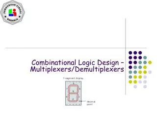
34. Code Converters BCD-to-Seven Segment Converters
4-bit BCD into a 7-bit code to drive display segments
Useful in calculators and any application that requires a 7 segment display.
35. Code Converters Gray Code
used to indicate angular position of rotating shafts
varies by only 1 bit from one entry to the next
36. Code Converters Gray Code
Comparison between regular binary and Gray code:
37. Code Converters Conversion between binary and Gray code using XOR gates
Figure 8-26 and 8-27
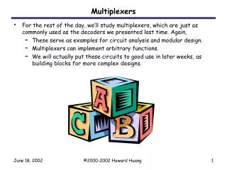
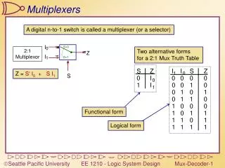
38. Multiplexers Funneling several data lines into a single one for transmission to another point
Data selector
Figure 8-30
39. Multiplexers
40. Multiplexers Logic diagram for a four-line multiplexer:
41. Multiplexers 74151 Eight-Line Multiplexer logic symbol � Figure 8-32
42. Multiplexers 74151 Eight-Line Multiplexer logic diagram � Figure 8-32(continued)
43. Multiplexers Providing Combination Logic Functions
Multiplexers can be used to implement combinational logic circuits.
A multiplexer can replace several SSI logic gates
Example 8-12
45. Demultiplexers Opposite procedure from multiplexing
Data distributor
Single data input routed to one of several outputs
Figure 8-37
46. Demultiplexers 74139 Dual 4-line Demultiplexer logic symbol and logic diagram- Figure 8-38
47. Demultiplexers 74139 connected to route an input signal to the 2a output � Figure 8-39
48. Demultiplexers 74154 4-line-to16-line hexadecimal decoder
Used as a 16 line demultiplexer
Connected to route a signal to the 5 output � Figure 8-40
49. Demultiplexers Analog Multiplexer/Demultiplexer
4051, 4052, 4053 CMOS devices
Both functions
Bidirectional
Analog and digital
50. 4051 CMOS analog multiplexer/demultiplexer � Figure 8-41
51. System Design Applications The 74138 as a memory address decoder � Figure 8-42
52. System Design Applications The 74148 used to encode an active alarm � Figure 8-43
53. System Design Applications Serial Data Multiplexing for a Microcontroller
One serial receive line
One serial transmit line
See Figure 8-44
Analog Multiplexer
superimposed
4051
See Figure 8-45
56. System Design Applications Multiplexed Display Application
Share common ics, components and conductors
Digital bus and display bus
See Figure 8-46
58. CPLD Design Applications Used to simulate combinations of inputs and observe the resulting output to check for proper design operation.
See CPLD Applications 8-1 and 8-2
59. Summary Comparators can be used to determine equality or which of two binary strings is larger.
Decoders can be used to convert a binary code into a singular active output representing its numeric value.
Encoders can be used to generate a coded output from a singular active numeric input line.
60. Summary ICs are available to convert BCD to binary and binary to BCD.
The Gray code is useful for indicating the angular position of a shaft on a rotating device, such as a motor.
Multiplexers are capable of funneling several data lines into a single line for transmission to another point.
61. Summary Demultiplexers are used to take a single data value or waveform and route it to one of several outputs.