Download

1 / 24
240 likes | 460 Vues
JEOL 5DII Operation introduction. By Serge Charlebois July 2003. Loading the cassette in the load lock Selecting EOS mode, table and aperture Setting and maximising current Observation mode Using the 4 th lens in 5 th lens modes Moving the stage (1)

E N D
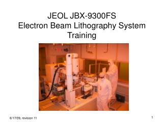
JEOL 5DIIOperation introduction By Serge Charlebois July 2003
Loading the cassette in the load lock Selecting EOS mode, table and aperture Setting and maximising current Observation mode Using the 4th lens in 5th lens modes Moving the stage (1) Setting focus, centering the aperture and correcting astigmatism Loading the cassette onto the exposure stage Using the CALIB program Moving the stage (2) Getting closer to exposure time… Correcting for stage rotation and image distortion Setting the table for mark detection Mark detection adjustment General procedure
Turn the load lock door handle and press the flashing red VENT button When the door opens depress the VENT button to stop the N2 flow The cassette must be inserted in the load lock with the copper handle facing to the right of the of the load lock, i.e. towards the manipulator arm. Close the door and turn the door handle into locking position Manipulator Cassette F LoadLock Cassette JEOL User Loading the cassette in the load lock (1) In the JEOL, the sample will be viewed in the same way as seen in the cassette when held with the copper handle to the right (the F in the illustration will be viewed as is in the JEOL)
The AUTO LOADER section is located at the upper far right of the console Loading the cassette in the load lock (2) • To be able to open the load lock, the elevator must be in initial position • Once loaded and inserted in the load lock • the filled cassette position should be marked by a green LED in the cassette column • The STEP UP green LED should also be lit to indicate that the cassette holder in is the right position (must be tightly screwed in) STAGE INITIAL These LED indicate the used cassette slots STEP UP
Selecting EOS mode and table • Log on to the FYVAX7 in the DEC terminal window • Start the CALIB program • enter DEC as the terminal type • enter the EOS mode as chosen in the conversion process • enter the EOS table assigned to you for this EOS mode (see user table) • Start the RESTOR routine to demagnetise the lens and return to a known/previous state of the column • Select the proper aperture • Function of the desired current (see beam current graphs)
Setting and maximising current (1a) • The column optimisation is done by maximising the current with the help of various alignment coils • The current is measured using a Faraday cup that must be placed under the beam • Use the CURREN routine in CALIB to have the Faraday cup positioned and current measured automatically. • This is the normal current measurement procedure
View of the picoammeteron the upper console with the door open Current value NORMAL mode Setting and maximising current (1b) • If the current value obtained is closed to the desired value • The column is close to optimal alignment • Activate the NORMAL current measurement mode and go to Setting and maximising current (3) • If the current value obtained is far from that desired • The column is not well aligned • The tables might not have been used for a long time • The JEOL might have been realigned, etc. • Activate the NORMAL current measurement mode and go to Setting and maximising current (2)
XH XT YH YT Alternatively selected the G-AL coil and the 1-AL coil to enter the 8 parameters Setting and maximising current (2a)Setting the reference parameters • Example of reference parameter file entry • Enter the alignment coil parameters • Select G-AL and using the 4 knobs enter the values XH, XT, YH and YT • Select 1-AL and using the 4 knobs enter the values XH, XT, YH and YT 29-jun-03 Bengt Nilsson BIAS 46 FIL 15 G-AL XH = 104 XT = -305 YH = 119 YT = -146 1-AL XH = 65 XT = -191 YH = 59 YT = -20 10nA 2nd = 15666
Set the current Unselect 4TH and 5TH lens Press 2/3 then press 2ND Use the COARSE and FINE button above to set the value as in the reference file The current should now be approximately that stated in the reference file It may vary if you are not using the same aperture The lens panel is located in the middle of the lower console In all cases, do not use any value below ~13000. You might find proper current (low range) but it will be unstable and the beam spot will be deformed and potentially multiple First unselect 4TH and 5TH Then press 2/3 and then 2ND Setting and maximising current (2b)Setting the reference parameters
Use the left buttons with the 1-AL coil Use the right buttons with the 1-AL coil Setting and maximising current (3) • Set the current to the desired value • See Setting and maximising current (2b) • Select G-AL • Use the two left buttons to maximise • Select 1-AL • Use the two right buttons to maximise • Readjust the current to the desired value and repeat the maximisation cycle • For large currents you may have to repeat the cycle numerous times increasing the current by small amount every time • When satisfied • set to REMOTE measurement. See Setting and maximising current (1b) • Start CURREN routine on the computer and save the value
Focus adjustment Contrast and brightness with SEI Beam blanker Scanning area: Normal → wide area Rapid → small area SEI - Secondary electron detector Lens selection Scanning speed Magnification Contrast and brightness for the BEI detector Selection of the SEI or BEI detector Observation mode (1)Overview of the buttons used
You will occasionally need to use the JEOL to observe part of the stage/sample as one would do with a SEM Move the stage to the location you want to observe ex. start INIMSH routine Press the desired lens 4TH has a wider field of view and is therefore easier to use to locate objects Press SEI and confirm that the BLK (beam blanker) is off You should see a the beam scanning on the screen Adjust the brightness and contrast to obtain an image Use the RAPID SCAN switch (separate control panel) To scan rapidly a small area: better for focussing, etc. To scan slowly a large area: best for searching objects To use the BEI detector Press SEI (main console) Flip the SEI/BEI switch (separate control panel) to BEI Use the BRIGHTNESS and CONTRAST button on that panel Observation mode (2)
An object placed at this position as viewed with the 4th lens will be at center when viewed with the 5th lens Using the 4th lens in 5th lens modes • In any mode, observation can be done using either the 4th of the 5th lens • The focus might be wrong as settings are independent for both lens • The exposure will be done with the lens designated by the EOS mode • The is a displacement between images observed by the two lenses 5th → 4th x,y → x+~140µm, y-~55µm
Increments Continuous motion in the chosen direction Position and direction indicatoron the upper console Select a direction Moving the stage (1) • To move the stage • Select a direction • Note that the referential is inverted • X and Y directions can be selected by pressing simultaniously • Press an increment button • ONE µm, 10µm, 100µm, 1mm and 5mm • The stage moves and a the position is indicated on the upper console • Use the CONT button to move the stage constinously in the selected direction • Ex. to move to exchange position, select –X and –Y and press CONT
Focussing using routines in CALIB Start INIMSH to move to the mesh marks, locate one of them and establish stage reference system If the mark is not found you will have to adjust the mark detection parameters (see Mark detection adjustment) Start the FOCUS routine to focus on the mark present in the center of the field The computer automatically select the EOS mode lens To focus manually Select the desired lens 4TH or 5TH (focus settings are specific to each lens) Press SEI to enter observation mode and set proper brightness and contrast Use the COARSE and FINE button to set the focus Look for sharp features and small details. Start at small magnification and increase it gradually looking at smaller details Setting focus
The aperture is a small hole that has to be centered in the column using To do so, you enter the WOB mode (wobbling) Unselect all lenses and coils Press WOB Select the desired lens The focus will now change in an oscillatory manner (wobble) resulting in a displacement of the image if the aperture is not centered Center the aperture using the 4 arrow buttonsof the stepping motor remote control To turn off wobbling mode Unselect the lens Press CLR on the right of WOB 1st: unselect all 2nd: WOB 3rd: select the proper lens Centering the aperture
The astigmatism of the beam spot is corrected using coils To correct the astigmatism Enter observation mode et locate small objects with sharp angles or details Press ASTIG Note the values indicates and the value of the focus Use the X and Y buttons to correct any astigmatism You can also slightly change the focus around optimal value while correcting It is also possible to use the wobbling mode while correcting astigmatism Unselect all lenses and coils Press WOB Select 4TH or 5TH Select ASTIG Note the values indicates Use the X and Y buttons to correct any astigmatism The focus is nowwobbled automatically Correcting astigmatism
Line up the elevator with the desired cassette Indicates that the stage is in exchange position and can be loaded Indicates that a cassette is on stage To open and close the gate valve To transfer the cassette from/to the stage To bring the elevator to initial position (ex. for loading cassette) To bring the elevator to the proper cassette Loading the cassette onto the exposure stage • Verify that the load lock is adequately pumped • Bring the stage to the loading position • The STAGE INITIAL LED will light up and the stage arrows (upper console) will flash • Bring the elevator to the proper cassette • Press STEP UP as needed to have a red LED facing the cassette to be loaded • Press OPEN to open the gate valve • Press TRANS to transfer the cassette onto the stage • Press OPEN to close the gate valve • The unloading procedure is similar
The program has two modes toggled by PF4 In TEMPORARY mode the routines are executed In PARAMETER mode the parameter used by the routines can be modified To execute a routine, Select it with the arrow keys and press ENTER Answer N to the following question To modify the parameters for one run only Select it with the arrow keys and press ENTER Enter Y and the desired parameters. Press PF1 (EXIT) to store and execute the routine Press PF2 (QUIT) to quit without modifying the parameters and executing the routine If you have selected a wrong routine, there is no direct way to cancel Answer Y to the “Modify parameters” Then press PF2 (QUIT) to exit without executing the routine To leave the CALIB program without saving any modification to the table press PF2 (QUIT) To leave the CALIB program and save the modified tables Select the SAVE routine, then GO, then Y and confirm with Y at the end Press PF1 (EXIT) and then Y to save the table The SAVE routine and the “save” option when exiting do not operate the same way. Only the SAVE routine seems to save the whole table Using the CALIB program (1)
The stage can be moved using two routines in CALIB Start STGCOM Enter absolute motions by typing MV [x value],[y value] Enter relative displacements by typing RS [x value],[y value] For other commands see CALIB manual (use HE for help) Exit the routine to regain control of the console STGMOV Offers a selection of predefined positions on the stage Using this routine can lock up the console in remote mode Start the LOCAL routine in CALIB to regain control of the JEOL Moving the stage (2) 0 : EXIT 1 : MESH MARK 2 : WIRE MARK 3 : FARADAY CUP 4 : SEM SPECIMEN 5 : KNIFE EDGE 6 : RESOLUTION SPECIMEN 7 : AUXILIARY-1 8 : AUXILIARY-2 9 : CASSETTE EXCHANGE 10 : BEAM CATCHING HOLE
You now have Aligned the column and set the current to the desired value Set a proper focus on the stage or sample Located the sample and noted the position for the exposure You should now Verify that the mesh mark detection works (INIMSH) If not, set the mark detection parameters Verify that the rotation correction works (PDEF) Correct for distortion (DISTOR) and save the results If alignment to a previous pattern is required Set the mark size, type and positions in SETWFR Execute SETWFR to verify that the marks are properly detected If not, adjust the mark detection parameters and enter them in You should now SAVE the tables and exit CALIB Validate and compile (CMPL) the JOBDECK file (.JDF) Validate and schedule (SCHD) the schedule file (.SDF) Expose the “magazin” file Getting closer to exposure time…
If a mark detection does not work, the parameter table has to be adjusted Ex. you use a different current as the usual one Ex. the structure/substrate contrast is low Position yourself on the desired mark Press SEI, then MD, then ADD and use normal (wide) scan Set the MAG and SPD to Adjust ATTEN to get peeks of equal height Adjust LEVEL to get a proper logical waveform Note the values and report them in the CALIB settings ADD ATTEN LEVEL SEI MD Mark detection adjustment (1)
The mark detection settings used in routines INIMSH, PDEF, DISTOR, FOCUS and others are set independently The routine SETMDG can be used to set all these parameters at once Start SETMDG Enter the parameters suitable for INIMSH The routine will then use the same values for other routines Follow the same logic for parameters for wafer mark detection This set the parameters for wafer mark detection and chip mark detection REMARK: the settings are not saved properly by using only the PF1 to exit CALIB Use the SAVE routine Then PF1 and save again Mark detection adjustment (1)The SETMDG routine
Stage coordinates The uses a left handed Cartesian system The center of the cassette is at coordinates 87000,60000 The exposure is done using an other coordinate system It is a right handed Cartesian system In this system, the center of the cassette is at (0,0) Use program OFFSET to convert between coordinates in the stage referential (as read on the console) and the exposure coordinates (as entered in the OFFSET command of JDF or SDF files) Cassette +X +Y (100,100) Exchange position Mesh marks Faradaycup (87000,60000) Coordinate systems