Drawing Plane Graphs by Takao Nishizeki at Tohoku University
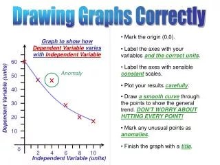
Explore objectives of graph drawings, from nice to modern beauty, achieving easy understandability using different methods like straight line, convex, and grid drawings. Learn about minimum grid size requirements and efficient algorithms. Understand the concept of convex grid drawing and find out the best possible algorithm for drawing plane graphs. Discover the process for creating a nice graph representation that is easy to comprehend.
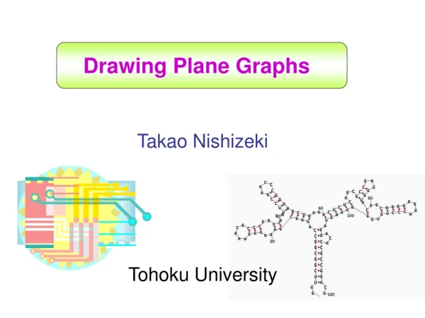

Drawing Plane Graphs by Takao Nishizeki at Tohoku University
E N D
Presentation Transcript
Drawing Plane Graphs Takao Nishizeki Tohoku University
US President California Governor
US President California Governor What is the common feature?
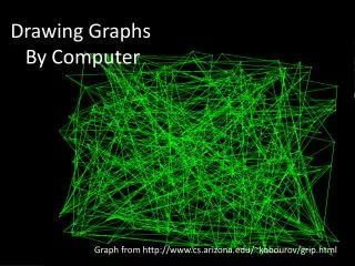
STATION STATION STATION STATION STATION ATM-HUB ATM-RT ATM-RT ATM-SW STATION STATION TPDDI ATM-HUB ATM-SW ATM-RT ATM-SW STATION STATION ATM-HUB STATION ATM-SW TPDDI ATM-SW STATION TPDDI STATION ATM-HUB ATM-HUB ATM-RT STATION STATION STATION STATION STATION STATION Graphs and Graph Drawings A diagram of a computer network
Symmetric Eades, Hong Objectives of Graph Drawings Nice drawing structure of the graph is easy to understand structure of the graph is difficult to understand To obtain a nice representation of a graph so that the structure of the graph is easily understandable.
Modern beauty Objectives of Graph Drawings Nice drawing Ancient beauty
8 7 5 6 4 3 2 1 Objectives of Graph Drawings Diagram of an electronic circuit 5 Wire crossings 7 4 8 3 1 2 not suitable for single layered PCB suitable for single layered PCB The drawing should satisfy some criterion arising from the application point of view.
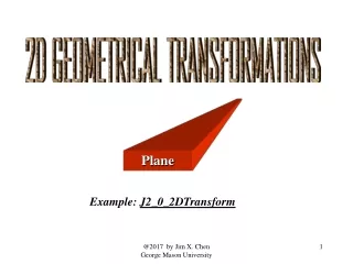
Drawings of Plane Graphs Straight line drawing Convex drawing
Drawings of Plane Graphs Rectangular drawing Box-rectangular drawing Orthogonal drawing
Book Planar Graph Drawing by Takao Nishizeki Md. Saidur Rahman http://www.nishizeki.ecei.tohoku.ac.jp/nszk/saidur/gdbook.html
Straight Line Drawing Plane graph
Straight Line Drawing Straight line drawing Plane graph
Straight Line Drawing Straight line drawing Plane graph Each vertex is drawn as a point.
Straight Line Drawing Straight line drawing Plane graph Each vertex is drawn as a point. Each edge is drawn as a single straight line segment.
Every plane graph has a straight line drawing. Wagner ’36 Fary ’48 Straight Line Drawing Polynomial-time algorithm Straight line drawing Plane graph Each vertex is drawn as a point. Each edge is drawn as a single straight line segment.
W H Straight Line Drawing W H Straight line drawing Plane graph
Straight Line Grid Drawing Straight line grid drawing. Plane graph In a straight line grid drawing each vertex is drawn on a grid point.
Wagner ’36 Fary ’48 Grid-size is not polynomial of the number of vertices n Straight line grid drawing. Plane graph
Straight Line Grid Drawing Straight line grid drawing. Plane graph de Fraysseix et al.’90
Chrobak and Payne ’95 Linear algorithm Straight line grid drawing. Plane graph de Fraysseix et al.’90
Schnyder ’90 H n-2 n-2 W Upper bound
What is the minimum size of a grid required for a straight line drawing?
A restricted class of plane graphs may have more compact grid drawing. Triangulated plane graph 3-connected graph
4-connected ? disconnected not 4-connected
Straight line grid drawing Miura et al. ’01 Input: 4-connected plane graph G Output: a straight line grid drawing Grid Size : H <n/2 = Area: W < n/2 =
Area < 1/4 = Miura et al. ’01 Schnyder ’90 4-connected plane graph G plane graph G n-2 H <n/2 = W < n/2 n-2 = . Area=n Area<n /4 . 2 2 =
The algorithm of Miura et al. is best possible
Triangulate all inner faces Step1: find a 4-canonical ordering G” n=18 n-1=17 n=18 n-1=17 16 16 Step2: Divide G into two halvesG’ and G” 15 15 12 12 14 14 10 10 13 13 11 11 9 n/2=9 8 8 5 5 6 6 7 7 4 4 Step3 and 4 : Draw G’ and G” in isosceles right-angled triangles 3 3 1 2 1 2 G’ G” W/2 G 1 |slope|>1 |slope|>1 |slope|>1 Step5: Combine the drawings of G’ and G” n/2 W/2 |slope|<1 = G’ W < n/2 -1 n/2 -1 = Main idea G
Draw a graph G on the plane “nicely” Straight line drawing A convex drawing is a straight line drawing where each face is drawn as a convex polygon. Convex drawing
Convex Drawing Convex drawing Tutte 1963 Every 3-connected planar graph has a convex drawing. A necessary and sufficient condition for a plane graph to have a convex drawing. Thomassen ’80
Convex Drawing Chiba et al. ’84 O(n) time algorithm Convex drawing Tutte 1963 Every 3-connected planar graph has a convex drawing A necessary and sufficient condition for a plane graph to have a convex drawing. Thomassen ’80
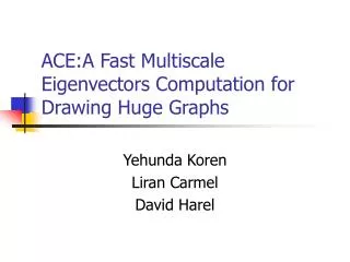
Convex Grid Drawing Chrobak and Kant ’97 Input: 3-connected graph Output: convex grid drawing n-2 n-2 Grid Size Area
Convex Grid Drawing Miura et al. 2000 Input : 4-connected plane graph Output: Convex grid drawing H Grid Size W Half-perimeter Area
Area < 1/4 = Miura et al. 2000 Chrobak and Kant ’97 3-connected graph 4-connected graph n-2 H n-2 W Area Area
The algorithm of Miura et al. is best possible H W
21 20 18 19 17 15 12 14 16 11 13 10 9 8 6 7 3 5 4 2 1 21 20 18 19 16 17 11 12 14 15 10 9 7 8 4: Decide y-coordinates 6 13 3 4 5 1 2 Main idea 20 21 19 18 17 14 15 13 10 16 12 11 9 6 8 7 3 4 5 1 2 1: 4-canonical decomposition 2: Find paths O(n)[NRN97] 3: Decide x-coordinates Time complexity: O(n)
VLSI Floorplanning B A F E C G D Interconnection graph
VLSI Floorplanning B B A A F F E E C G C G D D VLSI floorplan Interconnection graph
VLSI Floorplanning B B A A F F E E C G C G D D VLSI floorplan Interconnection graph
VLSI Floorplanning B B A A F F E E C G C G D D VLSI floorplan Interconnection graph
B A F E G C D VLSI Floorplanning B B A A F F E E C G C G D D VLSI floorplan Interconnection graph Dual-like graph
B B A A F F E E G G C C D D VLSI Floorplanning B B A A F F E E C G C G D D VLSI floorplan Interconnection graph Dual-like graph Add four corners
B B A A F F E E G G C C D D VLSI Floorplanning B B A A F F E Rectangular drawing E C G C G D D VLSI floorplan Interconnection graph Dual-like graph Add four corners
Rectangular Drawings Plane graph G of Input
Rectangular Drawings corner Rectangular drawing of G Plane graph G of Output Input
Rectangular Drawings corner Rectangular drawing of G Plane graph G of Output Input Each vertex is drawn as a point.
Rectangular Drawings corner Rectangular drawing of G Plane graph G of Output Input Each vertex is drawn as a point. Each edge is drawn as a horizontal or a vertical line segment.
Rectangular Drawings corner Rectangular drawing of G Plane graph G of Output Input Each vertex is drawn as a point. Each edge is drawn as a horizontal or a vertical line segment. Each face is drawn as a rectangle.